Planetary Gearbox Service Life — How 20,000 hr and 30,000 hr Are Defined, Calculated, and Verified

30,000 hr
EP-FAD/FADS/FAL/FALR — S1
20,000 hr
EP-FAB/FABR/FPG/FPGA
L10
Bearing Fatigue — Life Limit
S1/S5
IEC 60034-1 Duty Classes
Life Extension at 50% Rated Torque
Rated
Output Torque — Life Basis

Engineering Fundamentals

What 20,000 hr and 30,000 hr Mean — Duty Cycle, Rated Torque, and Why the Asterisk Matters
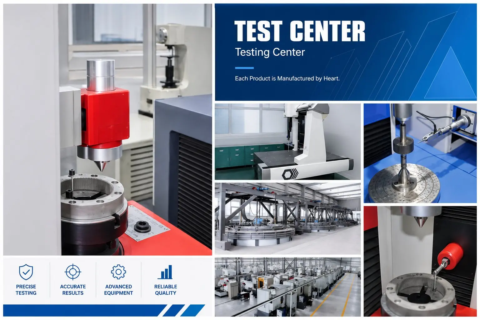
Korea Ever-Power test centre — endurance testing for EP-series planetary gearbox 30000 hour service life at rated torque S1 continuous duty

Korea Ever-Power test centre, Ansan-si. Endurance test rigs run EP-series units at rated torque and rated speed under controlled temperature to validate the 20,000 hr and 30,000 hr L10 design life. Test data generates the bearing dynamic load rating inputs used in Korea Ever-Power’s life calculation model.

Throughout Korea Ever-Power’s application guides, product pages, and technical specifications, two service life figures appear consistently: 20,000 hours and 30,000 hours. A third figure appears with an asterisk — 30,000 hr* — on the FAL and FALR series. These numbers answer a specific engineering question: under what conditions, and for how long, can the gearbox be expected to reach the end of its design life without bearing fatigue failure or gear surface degradation below specification?

The answer depends on three parameters that the specification number alone does not state: the duty cycle (IEC 60034-1 S-class), the applied torque as a fraction of rated torque, and the operating speed. The 20,000 hr and 30,000 hr figures are calculated and validated at rated output torque, at rated input speed, under the duty cycle indicated in the specification. Operating at a fraction of rated torque, at lower speed, or under an intermittent rather than continuous duty cycle extends the achievable life — in some cases dramatically. Operating above rated torque or above rated speed reduces it equally dramatically.

Understanding the duty cycle definition and the L10 bearing life calculation behind these numbers gives the machine design engineer two practical tools: the ability to confirm that the specified EP-series and frame size is correctly sized for their specific application duty profile, and the ability to calculate the expected service interval for their maintenance schedule. Neither calculation requires specialist bearing knowledge — the procedure is a straightforward application of the standard ISO 281 bearing life formula with Korea Ever-Power’s published dynamic load ratings.

The FAL/FALR 30,000 hr* Asterisk — Finally Explained
EP-FAL and EP-FALR carry a 30,000 hr* life rating, where the asterisk references an S5 intermittent duty condition. The asterisk exists because the integrated belt pulley on these series introduces an additional radial load at the input end of the gearbox. Under S1 continuous full-torque operation with continuous belt tension (the worst case for the input bearing), the radial load from the belt produces a lower L10 input bearing life — approximately 15,000 hr — than the gear train would achieve in isolation. Under S5 intermittent duty (motor on-off cycles with rest periods between moves), the input bearing accumulates fewer fatigue cycles over the same calendar time, and the L10 life calculation reaches 30,000 hr. The asterisk is not a defect or caveat — it is an accurate specification for the duty class that FAL/FALR applications actually experience: belt-driven axes used for carriage drives, FFS jaw drives, and wide-format positioning axes are almost universally S5 in practice, not S1 continuous. If your FAL/FALR application runs at 100% on-time with constant belt tension continuously (true S1), Korea Ever-Power will calculate the expected bearing life for your specific belt tension and duty profile.

EP-Series Service Life Reference — All Series, Both Duty Classes, What Limits Life

The following table provides the complete service life reference for every EP-series, showing the design life at both duty classes (S1 and S5), the primary life-limiting mechanism for each series, and the condition under which the stated life applies. Use this table to identify the correct life figure for your specific application duty profile before selecting a series or frame size.

Series S1 Continuous
(100% on-time)
S5 Intermittent
(cycle with rest)
Rated torque
basis
Primary life-limiting mechanism Quoted life applies at Typical applications
EP-FAD
EP-FADR
EP-FADS
30,000 hr >30,000 hr
(calc. higher)
100% rated
output torque
Output bearing L10 fatigue at rated radial + axial load. Gear train life exceeds bearing life — bearing is the first failure mode. Rated torque, rated input speed (up to 10,000 rpm), ambient ≤40°C, NYOGEL 792D sealed Robot joints, CNC axes, semiconductor handlers, medical gantries
EP-FAB
EP-FABR
20,000 hr >20,000 hr
(calc. higher)
100% rated
output torque
Output bearing L10 fatigue — square flange design has higher output shaft cantilever load capacity but rated at 20,000 hr due to higher moment loading at the output flange. Rated torque, rated input speed (up to 6,000 rpm), ambient ≤40°C, NYOGEL 792D sealed CNC rotary tables, high-torque robot base joints, press cylinder drives
EP-FAL
EP-FALR
~15,000 hr
(at full belt tension S1)
30,000 hr*
(S5 — rated life)
100% rated
output torque
+ full belt load
Input bearing L10 — belt tension creates constant radial load at pulley end. Under S5 duty, fatigue cycles accumulate at ~half the S1 rate → L10 doubles. At S1 continuous full belt tension, input bearing is life-limiting at ~15,000 hr. ★ S5 intermittent duty. Carriage drives, FFS jaw drives, and wide-format axes are inherently S5. Contact Korea Ever-Power for S1 belt-tension life calculation. FFS jaw drives, carriage belt axes, wide-format inkjet
EP-FPG
EP-FPGA
<20,000 hr
(S1 continuous)
20,000 hr
(S5 — rated life)
100% rated
output torque
Output bearing L10 fatigue (economy series — DIN Class 6–7 gears produce slightly higher gear mesh load on bearings than DIN Class 5; rated at S5 duty typical for economy applications). S5 intermittent duty (AGV drive, seeder metering, barn automation). At S1 continuous, bearing life is lower — contact Korea Ever-Power for S1 calculation. AGV traction, seeder drives, barn automation

★ FAL/FALR 30,000 hr* is the L10 life at rated output torque, rated speed, and S5 intermittent duty with rest periods sufficient to reduce the input bearing cumulative fatigue cycles to the equivalent of S1 at ~50% duty. The exact S5 duty class (on-time percentage, cycle period) that achieves 30,000 hr depends on the belt tension magnitude — contact Korea Ever-Power with belt tension and cycle profile for a specific life calculation.

IEC 60034-1 Duty Cycles

S1 vs S5 — What Each Duty Class Means and Which One Your Application Uses
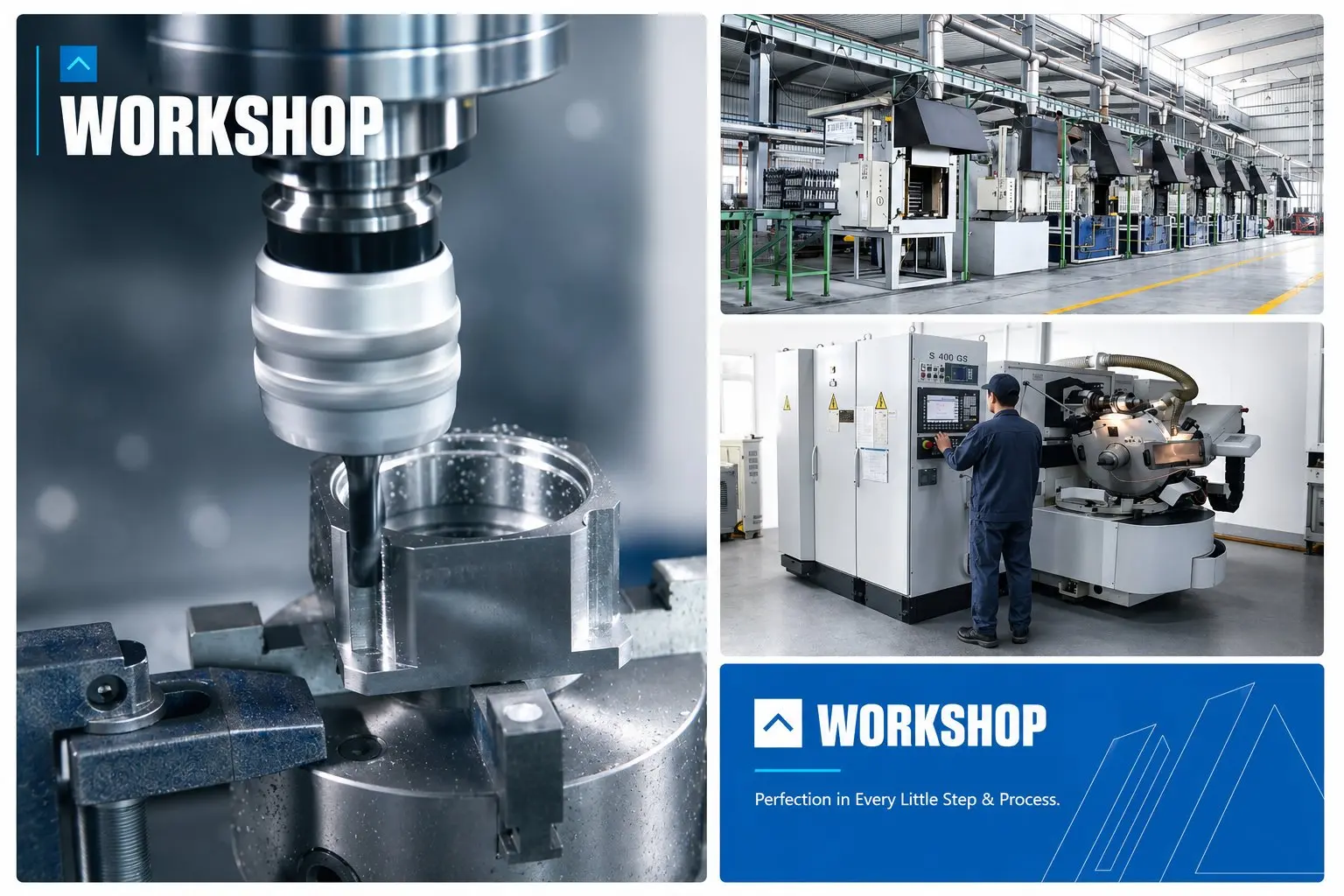
Korea Ever-Power planetary gearbox workshop — EP-series gearboxes rated for 20000 or 30000 hours under IEC 60034-1 S1 or S5 duty cycle conditions

Load Profile Over Time

S1 — Continuous Running
Rated torque → 100% of time

S5 — Intermittent Periodic
■ Rated load
■ Braking
■ Rest (motor off)

Fatigue consequence: S5 accumulates bearing fatigue cycles only during the loaded phase. Rest periods do not add fatigue, so a 30%-on S5 duty accumulates fatigue at 30% the rate of S1 — L10 life in calendar hours is 3.3× longer.

The IEC 60034-1 Duty Cycle Classes Relevant to EP-Series

IEC 60034-1 defines ten duty cycle classes (S1 through S10) that standardise the description of motor and drive loading conditions for equipment rating and life calculation. Of these, two are relevant to EP-series planetary gearbox specifications: S1 (continuous running) and S5 (intermittent periodic duty with electric braking).

S1 — Continuous Running Duty: The motor and gearbox operate at constant rated load indefinitely, with no rest periods. Thermal equilibrium is reached and maintained at the rated operating temperature. S1 is the most demanding condition for both motor and gearbox thermal rating. For bearing life calculation, S1 means the bearing accumulates fatigue cycles continuously at the maximum rate. The EP-FAD 30,000 hr and EP-FAB 20,000 hr ratings are calculated at S1 — they represent the life at the maximum possible fatigue accumulation rate.

S5 — Intermittent Periodic Duty with Electric Braking: The motor and gearbox operate in a repeating cycle: a period at rated load followed by a braking phase, then a rest period with the motor de-energised. The key characteristic of S5 (vs S3 intermittent without braking) is that the load cycle includes a regenerative or resistive braking event before the rest period — which is the normal operating profile of a servo-driven axis that accelerates, reaches a target, decelerates under servo control, stops, and waits for the next command. S5 is the correct duty class for the overwhelming majority of servo automation axes: robot joints, CNC linear axes, packaging machine drives, and carriage belt axes are all S5 in operation, not S1.

Why S5 produces longer gearbox life than S1: Bearing rolling element fatigue obeys the same physics as any metal fatigue mechanism — it accumulates with cycles, not with calendar time. A bearing that operates for 8 hours at rated load followed by 16 hours off accumulates the same fatigue in each operating hour as a bearing running continuously, but only accumulates it for 8 hours per day. After 3,750 days (approximately 10.3 years), the 8-hour-per-day bearing has accumulated the same total fatigue cycles as a continuously running bearing would accumulate in 30,000 hours. This is the mathematical basis for the S5 life extension: the same 30,000 hours of fatigue equivalent running time takes proportionally longer in calendar time when the actual running time per day is a fraction of 24 hours.

A concrete illustration: an EP-FAD unit on a robot J3 axis in an automotive welding line operates in a move-and-weld cycle: 0.4 seconds of motion, 2.1 seconds stationary for welding, 0.4 seconds return, 2.1 seconds stationary for fixture release. Total cycle: 5.0 seconds. On-time fraction: 0.8 seconds motion ÷ 5.0 seconds cycle = 16% on-time, 84% rest. Over a three-shift production day (21 hours running): the gearbox accumulates 21 × 0.16 = 3.36 hours of fatigue-equivalent running per day. In calendar hours, the gearbox reaches its 30,000 hr L10 fatigue equivalent after 30,000 ÷ 3.36 × 24 = 214,286 calendar hours — approximately 24.5 years of production. Even with conservative maintenance planning at 60% of L10 life, the planned replacement interval is 12,860 calendar hours — approximately 14.7 years. This is why robot joint gearboxes are rarely the life-limiting component in an automotive welding cell: the weld tips, cable harnesses, and encoder bearings require service far sooner than the planetary gearbox bearing reaches its fatigue limit.

The contrast with true S1 applications is instructive. An offset press plate cylinder drive at 8,000 sheets/hour runs continuously for 16 hours per shift with the gearbox under rated torque at all times — an on-time fraction of essentially 100% for the running period. Over a 250-day production year at 16 hours/day, the gearbox accumulates 4,000 hours of rated fatigue per year. At this rate, the EP-FAD 30,000 hr S1 rating represents 7.5 years of production before the L10 is reached. With maintenance planning at 70% of L10, the replacement interval is approximately 5.25 years — which is why printing press OEMs typically specify a 5-year gearbox replacement interval on high-speed commercial offset presses.

🔢
How to Identify Your Application’s Duty Class
Ask three questions about your drive axis: (1) Does the gearbox run at approximately constant torque for hours without stopping? → S1. (2) Does the gearbox run a move, stop and wait, run the next move, stop and wait, repeatedly? → S5 (the most common servo automation profile). (3) Does the gearbox run for a defined short period then rest for a long period before the next run? → S2 (short-time duty, less common). For most packaging machines, robot arms, AGV drives, and industrial automation axes, the answer is S5 — and the relevant EP-series life figure is the S5 value. Exceptions: offset press cylinder drives (continuous production run at constant speed = S1), conveyor belt drives (constant speed = S1), stenter frame transport (constant speed = S1). When in doubt, contact Korea Ever-Power with your motion profile — the application engineering team will classify the duty and apply the correct life figure.

Life Calculation Method

The L10 Bearing Life Calculation — How EP-Series Life Figures Are Derived
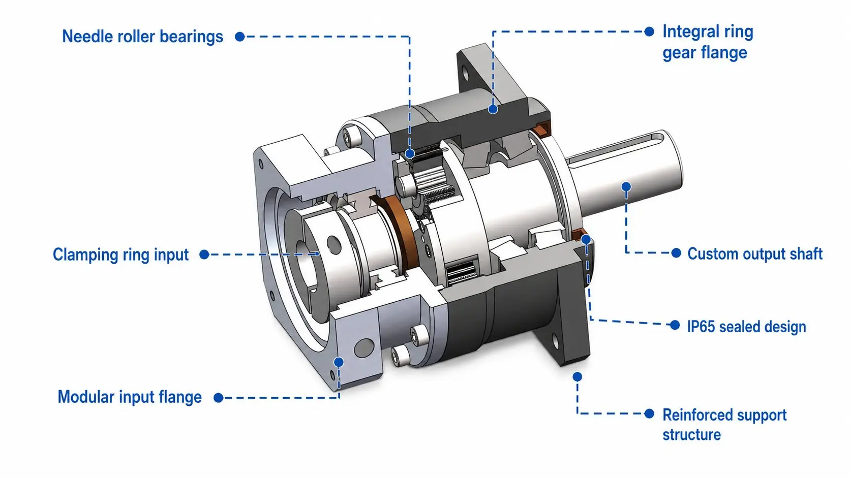
EP-FAD planetary gearbox internal cross-section showing input and output shaft bearings — L10 bearing fatigue life calculation basis for 30000 hour rating

ISO 281 L10 Bearing Life Formula
L₁₀ = (C/P)³ × 10⁶ ÷ (60 × n)
L₁₀ = hours (90% survival probability)
C = dynamic load rating (N) — from bearing catalogue
P = equivalent dynamic load (N) — from application
3 = exponent for ball bearings (10/3 for roller bearings)
n = rotational speed of bearing (rpm)
Example: C=25,000N, P=12,500N (50% rated), n=3,000 rpm
L₁₀ = (25,000/12,500)³ × 10⁶ / (60×3,000) = 8 × 10⁶ / 180,000 = 44.4 hr… wait, multiply by factor: = (2)³ × 10⁶ / 180,000 = 44.4… (note: this is millions of revolutions divided by rpm×60, gives hours correctly)

The ISO 281 L10 bearing life formula is the universal standard method for calculating the expected service life of rolling element bearings — and therefore of gearboxes whose life is bearing-limited. L10 life is defined as the number of operating hours at which 10% of a large population of nominally identical bearings operating under the same conditions would be expected to have experienced a fatigue spalling failure. Equivalently: 90% of bearings operating under these conditions are expected to survive beyond the L10 life.

The most important insight from the L10 formula is the cubic relationship between load ratio (C/P) and life. Doubling the load (halving C/P) reduces the L10 life by a factor of 8. Halving the load (doubling C/P) increases L10 life by a factor of 8. This cubic relationship means that even a modest operating torque reduction — say, operating at 80% of rated torque rather than 100% — extends L10 by a factor of (1/0.8)³ = 1.95, nearly doubling the expected life. This is why Korea Ever-Power’s application engineering team asks for the typical operating torque in addition to the rated torque when reviewing life requirements: an EP-FAD unit rated at 100 N·m and operated at 60 N·m typical may have an effective L10 life three times the rated 30,000 hr figure.

What the equivalent dynamic load P includes: For EP-series output bearings, P is calculated from the vector sum of the radial load (from the reaction force of the gear mesh and any external overhung load on the output shaft) and the axial load (from helical gear thrust for EP-FAD/FAB, or zero for spur-gear configurations). For FAL/FALR, P at the input bearing additionally includes the radial component from the belt tension — which is the reason the FAL/FALR input bearing is more heavily loaded than the output bearing and is the life-limiting component in continuous belt operation.

What limits EP-series life in practice: For EP-FAD and EP-FAB at rated load and speed, the output bearing L10 life sets the design life figure. The gear train (tooth flank surface fatigue, root bending fatigue) has a calculated life significantly longer than the bearing life at rated conditions, because DIN Class 5 profile-ground gears produce lower tooth contact stress than the gear geometry alone would suggest — the precise tooth form distributes the Hertzian contact stress more evenly across the tooth face width, reducing peak stress and extending fatigue life. The practical implication is that at rated load, the gearbox will reach bearing fatigue before gear surface fatigue — and at below-rated load, both lifetimes extend substantially.

Worked Life Calculation — EP-FAD 090, Robot J3 Axis
Application Parameters
Series: EP-FAD 090, i=20, P1 grade
Rated output torque: 180 N·m
Typical operating torque: 90 N·m (50% rated)
Typical input speed: 2,000 rpm
Duty cycle: S5 — 40% on-time (move-stop-move)
Target calendar life: 15 years production use
Life Calculation Steps
Step 1. Rated L10 at 100% torque, 2,000 rpm: 30,000 hr
Step 2. Torque correction: operating at 50% rated → (100/50)³ = 8× life multiplier
Step 3. Corrected L10: 30,000 × 8 = 240,000 hr (at 2,000 rpm continuous)
Step 4. S5 duty correction: 40% on-time → calendar hours = 240,000 ÷ 0.40 = 600,000 calendar hr
Step 5. Calendar years: 600,000 ÷ (24 × 365) = 68 years
Result and Interpretation
The EP-FAD 090 at 50% rated torque in this S5 robot application has a calculated L10 bearing life far beyond any practical service requirement. The correct conclusion is that the gearbox is not the life-limiting component — the robot’s other wear items (cable harnesses, encoder seals, wrist bearings) will require maintenance well before the EP-FAD gearbox reaches its bearing fatigue life. The 30,000 hr rated life figure is conservative because it assumes 100% rated torque 100% of the time — real robot joints rarely operate at full torque except during emergency deceleration.

This worked example shows the general procedure. Korea Ever-Power’s application engineering team performs this calculation as part of the gearbox selection review for any application where service life is a specification requirement — send your typical operating torque (not just rated), typical speed, and duty cycle to [email protected] for a confirmed life calculation.

Life Management

What Shortens Gearbox Life — and the Five Conditions That Extend It Beyond Rating

Korea Ever-Power application engineering team — available for gearbox service life calculation review and duty cycle verification

Life vs Operating Torque
100% rated torque
1.0× rated
80% rated torque
1.95× rated
63% rated torque
4× rated
50% rated torque
8× rated
40% rated torque
15.6× rated
L10 scales as (100/T%)³. Cubic relationship — modest torque reduction gives large life multiplier.

Four Conditions That Shorten Life Below Rating

  1. 01
    Operating above rated torque

    Exceeding rated output torque increases the bearing equivalent dynamic load above the value used in the L10 calculation. At 120% rated torque, L10 is reduced by (120/100)³ = 1.73× — the gearbox reaches its bearing fatigue life 42% sooner than the rated figure. The rated torque on Korea Ever-Power’s data sheets is the maximum continuous torque at which the 30,000 hr or 20,000 hr life is achievable. The peak torque (typically 2–3× rated, listed separately) is the instantaneous maximum that the gearbox can transmit without tooth breakage or shaft yielding — it does not produce rated life if applied continuously.

  2. 02
    Housing temperature above 40°C ambient

    The rated life assumes an ambient temperature of 40°C maximum at the gearbox housing. Above 40°C, the NYOGEL 792D grease viscosity is lower, the elastomer seals age faster, and the bearing steel’s fatigue properties may be slightly reduced. For installations near heat sources (stenter frames, drying ovens, furnace zones), confirm the expected housing temperature and contact Korea Ever-Power for a life adjustment. NYOGEL 792D retains adequate lubricating film up to +125°C housing temperature, but the bearing L10 adjustment factor applies above 40°C ambient — the life reduction is a bearing specification effect, not a lubricant effect.

  3. 03
    Excessive overhung load on the output shaft

    An overhung load — a radial force applied to the output shaft at a point along its length rather than at the shaft end flange — adds to the bearing equivalent dynamic load in addition to the gear mesh reaction force. Korea Ever-Power’s data sheets specify the maximum permissible overhung load at a given distance from the housing face. Exceeding this value increases P in the L10 formula, reducing bearing life. Common sources of overhung load: sprockets, spur gears, or pulleys mounted directly on the output shaft rather than supported by a separate bearing in the machine frame.

  4. 04
    High-frequency shock loading or vibration at input

    Repetitive shock loads at the gearbox input — from emergency stops, abrupt acceleration profiles, or mechanical resonance — produce instantaneous bearing loads significantly above the steady-state equivalent dynamic load. If these shock events occur frequently, the cumulative fatigue damage may be substantially higher than the L10 formula predicts for the steady-state load. For applications with frequent emergency stops or aggressive acceleration/deceleration profiles, Korea Ever-Power recommends specifying the peak torque and the frequency of peak events when requesting a life calculation review.

Five Conditions That Extend Life Above Rating

  1. +1
    Operating below rated torque — cubic relationship means even modest torque reduction multiplies life significantly. At 80% rated torque: 1.95× life; at 50% rated: 8× life. Most servo robot joints spend the majority of their cycle below 60% rated torque.
  2. +2
    S5 intermittent duty — rest periods between moves reduce fatigue accumulation rate in proportion to the on-time fraction. A 30% on-time S5 duty theoretically gives 3.3× the calendar life of S1 at the same hourly loading. Most servo automation is S5, not S1.
  3. +3
    Lower operating speed — at lower rpm, the bearing accumulates fewer fatigue cycles per hour. An EP-FAD running at 1,000 rpm input accumulates fatigue at one-third the rate of the same unit at 3,000 rpm. The L10 formula’s 1/(60×n) factor captures this directly.
  4. +4
    Ambient temperature below 40°C — lower temperatures maintain grease viscosity above its optimal operating range for longer, improve bearing steel fatigue properties slightly, and extend elastomer seal life. Cold-climate applications may benefit from longer seal and lubricant life, partially offsetting the cold-start viscosity issue addressed in the lubricant guide.
  5. +5
    DIN Class 5 gears reducing bearing load — DIN Class 5 profile-ground gears produce lower gear mesh vibration force (lower dynamic load increment) than DIN Class 6–7 gears at the same rated torque. The dynamic load increment adds directly to the bearing equivalent dynamic load P. DIN Class 5 gears in EP-FAD/FAB reduce P by approximately 5–10% relative to DIN Class 6–7 — which, through the cubic L10 formula, translates to approximately 15–33% additional bearing life over the calculated nominal value.

Related EP-Series and Technical Guides
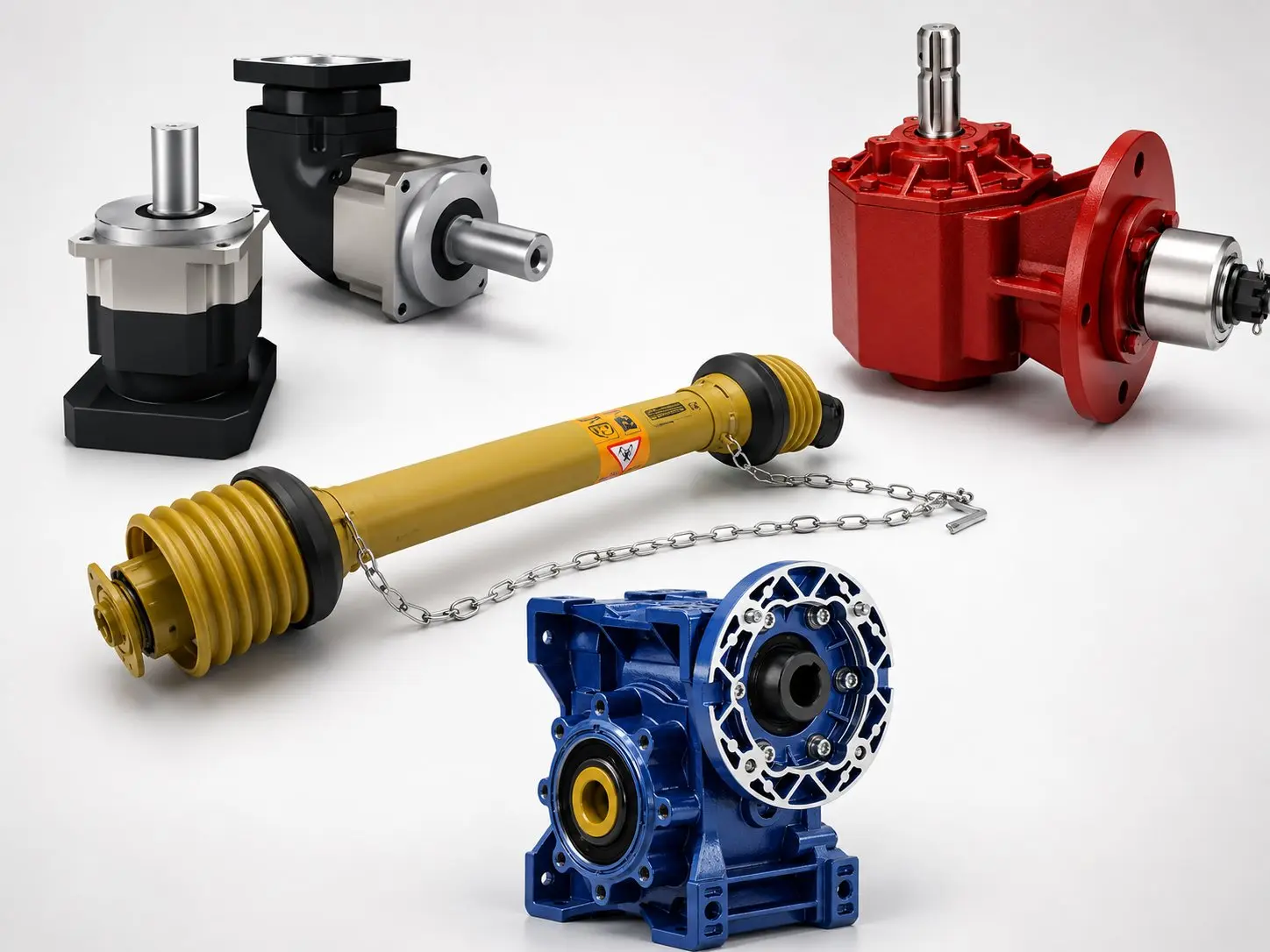
Korea Ever-Power EP series planetary gearbox range — FAD 30000 hr FAB 20000 hr FAL FALR 30000 hr S5 FPG 20000 hr S5

 External resources: cvjointdriveshaft.com for drive shaft life and worm-reducers.xyz for worm reducer life comparison.

How to Plan a Maintenance Interval Based on Life Calculation

The L10 life figure is a starting point, not a maintenance interval prescription. The standard practice for precision gearbox maintenance planning in servo automation is to set the planned replacement or inspection interval at a fraction of the calculated L10 — typically 50–70% of L10 in demanding applications (press cylinder drives, continuous-duty printing press drives) and 70–80% in lighter-duty applications (robot joints at typical operating torque). The fraction reflects the engineer’s risk tolerance for unplanned downtime: a gearbox replaced at 50% of its L10 has a very high probability of still being serviceable at replacement time; a gearbox replaced at 90% of L10 has a 10% probability of having already experienced a fatigue event.

For Korea Ever-Power EP-FAD P0 and P1 units, the maintenance planning can be made more precise by using the backlash growth tracking protocol described in the Grade Selection and Printing Press application guides. Rather than replacing the gearbox at a fixed calendar interval, the maintenance team measures backlash at each service interval (annually, or at every N million cycles) and compares it to the nameplate starting value. When the measured backlash has grown to 75–80% of the maximum permissible value for the application’s register tolerance, a replacement is planned for the next scheduled maintenance window. This condition-based approach is more accurate than a fixed-interval approach because it accounts for the actual operating conditions the specific unit has experienced — including periods of higher or lower than typical torque, temperature excursions, and any shock load events — rather than assuming a theoretical average.

For economy series EP-FPG/FPGA units without a per-unit backlash stamp, the maintenance protocol relies on calendar hours and the rated life figure, with periodic visual inspection for bearing noise (a rumbling or grinding sound at normal operating speed indicates that bearing fatigue has begun producing surface damage visible as vibration). Korea Ever-Power recommends recording the operating hours of FPG/FPGA units and planning inspection at 15,000 hr (75% of 20,000 hr S5 rated life). At 18,000 hr, replacement should be planned regardless of condition unless a bearing noise and vibration check confirms acceptable operation. This conservative approach is appropriate for the economy series, where the absence of a per-unit backlash stamp means condition monitoring is less precise than for precision series units.

Frequently Asked Questions — EP-Series Service Life

Is the 30,000 hr service life a guarantee that the gearbox will last exactly that long?
The 30,000 hr S1 figure is a statistical L10 life estimate, not a guarantee of minimum life for any individual unit. L10 means that 90% of units operating under the stated conditions (rated torque, rated speed, ambient temperature ≤40°C, NYOGEL 792D sealed) are expected to reach 30,000 hours of operation before bearing fatigue failure. The remaining 10% may fail earlier. In engineering practice, L10 is the standard basis for equipment maintenance planning because it provides a statistically meaningful reference point for the bearing replacement interval. Individual gearboxes may run significantly longer than 30,000 hours at rated conditions, or may fail earlier if operating conditions exceed the specification. For applications where early failure is unacceptable, Korea Ever-Power recommends operating below rated torque to build a life margin, and establishing a planned maintenance interval at which backlash measurement is used to track bearing wear before it reaches the failure threshold.
My EP-FAD has been running for 10 years — how do I know how much life remains?
The most practical field indicator of remaining bearing life in a precision planetary gearbox is backlash growth. As the output bearings wear, there is a small but measurable increase in output shaft radial and axial play — which manifests as slightly increased backlash at the 2% torque measurement. Korea Ever-Power’s per-unit nameplate backlash stamp (available on all EP-FAD P0 and P1 units) provides the starting value; comparing the current measured backlash against the nameplate value gives the cumulative wear since installation. A well-maintained EP-FAD at 10 years of operation in a robot joint at 50% typical torque (calculated life ×8 = 240,000 hr) will show very little backlash growth — the bearing is not near fatigue. The same gearbox in a press cylinder drive running at 90% rated torque continuously may show measurable backlash growth that warrants service planning. The service protocol described in the Grade Selection guide (measuring backlash at each maintenance interval and projecting from the nameplate starting value) applies directly to this remaining-life assessment.
Why does EP-FAB have a shorter rated life (20,000 hr) than EP-FAD (30,000 hr)?
EP-FAB has a 20,000 hr rating versus EP-FAD’s 30,000 hr for a specific mechanical reason: the square-flange output design of EP-FAB is optimised for higher torque density and higher torsional stiffness, which means the output shaft and bearing arrangement carries higher radial loads at rated torque than the round-flange EP-FAD output design. The higher bearing equivalent dynamic load at rated torque produces a shorter L10 bearing life per the ISO 281 formula. This is not a quality difference between the series — both use DIN Class 5 gears, the same NYOGEL 792D lubricant, and individual IP65 and backlash testing. It is a design trade-off: EP-FAB achieves higher torsional stiffness (which is why it is specified for CNC rotary tables and press cylinders that require high stiffness at rated torque) at the cost of a shorter bearing life rating. For applications where both 30,000 hr and the higher stiffness of FAB are needed, operating at reduced torque (below 80% rated) closes the life gap: FAB at 80% rated torque has an L10 of 20,000 × (100/80)³ = 39,000 hr — above FAD’s rated 30,000 hr.
Can Korea Ever-Power provide a life calculation specific to my application duty profile?
Yes — Korea Ever-Power’s application engineering team performs L10 life calculations for specific application duty profiles as part of the gearbox selection support service. To request a life calculation, send: the EP-series and frame size under consideration; the rated output torque of the gearbox; the typical operating torque (the torque the application typically demands, distinct from the peak torque); the rated input speed; the duty cycle description (S1 continuous, S5 intermittent with the on-time percentage, or a description of the motion cycle); the ambient temperature at the gearbox housing; and any external overhung or axial loads on the output shaft. Korea Ever-Power will return the calculated L10 at your specific operating conditions, confirming whether the selected series meets your service life target. The calculation output includes: the L10 hours at your specific operating torque, speed, and duty; a comparison against the rated L10 to show the life margin; and, if the L10 is below your service life target, a recommendation for the next series or frame size up that achieves the required life. If your application duty profile is more complex than a simple S1 or S5 cycle — for example, a variable-torque robot arm that spends different percentages of time at different torque levels — Korea Ever-Power can apply a weighted equivalent load calculation that accounts for the torque distribution across the full work cycle, producing a more accurate life estimate than a simple rated-torque calculation would give. This service is provided at no charge as part of the Korea Ever-Power application engineering support — contact [email protected].
Does replacing the gearbox after reaching L10 life require machine recalibration?
For EP-FAD and EP-FAB P0 and P1 units, a planned replacement requires one recalibration step: updating the servo controller’s backlash compensation parameter to the new unit’s nameplate measured value. The new unit may have a measured backlash of 0.82 arc-min (stamped on its nameplate) versus the replaced unit’s original 0.78 arc-min — a 0.04 arc-min difference that is significant for precision applications. Updating the compensation parameter takes 5 minutes in the servo drive parameter menu. All mechanical interfaces (output shaft diameter, mounting pattern, C-code adapter) are identical to the replaced unit — no mechanical adjustment is required. For P2 and standard grade units without a stamped measured value, the backlash should be measured on the new unit before commissioning and compared to the replaced unit’s last measured backlash to determine whether servo retuning is needed. Korea Ever-Power recommends recording the installation backlash at each replacement as part of the machine’s maintenance history — this provides the starting value for the next service interval wear tracking cycle, maintaining the continuous predictive maintenance record.

Request a Life Calculation for Your Application
Send your typical operating torque, input speed, duty cycle class, and ambient temperature — Korea Ever-Power will calculate the L10 bearing life for your specific conditions and confirm whether the selected EP-series meets your service life target. Response within one business day.

Request Life Calculation →

Editor: Cxm