Planetary Gearbox for SCARA Robots — Joint-by-Joint Selection Guide

>40%
Of All Robots Shipped Globally
J1–J4
Four Distinct Axis Requirements
P0
J1/J2 Grade — TCP <0.05mm
EP-FADS
J3/J4 Compact Direct-Insert
S5
Duty Cycle — Pick and Place
0.030mm
TCP Error at 300mm Radius, P0

Application Guide

Why SCARA Robot Gearbox Selection Is Different From 6-Axis — And Why Getting It Wrong Is the Leading Cause of Assembly Accuracy Problems

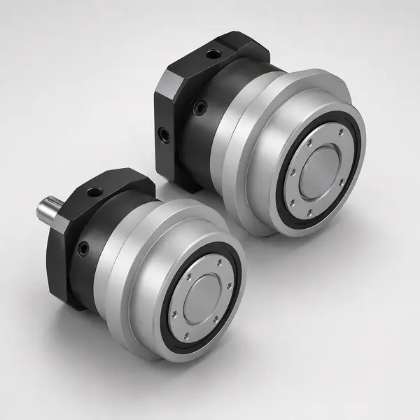
EP-FADS series direct-insert planetary gearbox — ideal for SCARA robot J3 Z-stroke and J4 tool rotation due to compact direct-insert design eliminating adapter plate crevice and reducing axial length

EP-FADS series direct-insert gearbox — the preferred choice for SCARA J3 (Z-stroke ballscrew drive) and J4 (tool rotation). The direct-insert design saves 22mm of axial length compared to EP-FAD with adapter ring, which is critical in the compact SCARA head assembly where J3 and J4 must fit within the robot’s wrist housing envelope.

SCARA robots — Selective Compliance Assembly Robot Arms — represent more than 40% of all robot units shipped globally. Their horizontal revolute arm structure makes them the dominant technology for high-speed pick-and-place, electronic component assembly, pharmaceutical dispensing, and precision part insertion where cycle time and TCP (Tool Centre Point) accuracy must both be maximised. Despite this dominance, the gearbox selection methodology for SCARA joints is significantly different from the 6-axis robot methodology covered in Korea Ever-Power’s Industrial Robotics guide — and confusing the two approaches is the most common cause of over-specification at J2/J4 (wasting budget) and under-specification at J1 (causing TCP accuracy problems at full arm extension). The global SCARA robot market spans an enormous range of performance classes: from low-cost 1-kg-payload SCARA units used in basic pick-and-place for under ¥50,000 CNY, to high-speed precision SCARA robots for semiconductor wafer handling at ten times the price. The gearbox specification spans a proportionally wide range — from economy EP-FPG P2 for the simplest pick-and-place where ±1mm TCP is sufficient, to EP-FAD P0 with individual measured backlash certification for semiconductor handling SCARA where ±0.02mm is the specification. This guide covers the precision end of that range, where backlash grade is a meaningful specification parameter — applications where P0 vs P1 choice makes a visible difference in TCP accuracy rather than being a theoretical distinction.

The key architectural difference is that SCARA J1 and J2 both move in the horizontal plane, carrying the full payload and tool weight as a moment load about a vertical axis. In a 6-axis robot, the arm weight is distributed across J1 through J3, each carrying a different fraction depending on the robot’s configuration and payload position. In a SCARA, J1 carries the full moment of the entire arm and payload at all times during horizontal movement — there is no configuration-dependent load reduction. This makes J1 the most heavily loaded joint in the SCARA, and its backlash grade is the dominant contributor to TCP accuracy at full arm extension.

J3 in a SCARA is a vertical linear stroke — not a rotary joint — and is typically driven by a ballscrew with a planetary gearbox input. The backlash that matters for J3 is the linear positioning accuracy of the Z-axis, which determines insertion depth accuracy in press-fit assembly and syringe dispensing applications. J4 is a pure rotation of the end-of-arm tool, carrying no significant moment load, and is the least demanding joint in terms of gearbox specification — though cycle count requirements for J4 are very high in high-speed SCARA applications, making S5 duty cycle life calculation relevant even for this compact joint.

⚙️
The SCARA Backlash Geometry Rule
In a SCARA with upper arm length R1 and forearm length R2: J1 backlash contributes to TCP error at the full combined arm radius (R1+R2). J2 backlash contributes to TCP error only at the forearm radius R2, scaled by the ratio R2/(R1+R2). For a typical SCARA with equal arm lengths (R1=R2=300mm): J2 backlash contributes only 50% of J1 backlash to the TCP error at maximum extension. This means J1 requires the tighter grade specification, while J2 can often tolerate one grade looser than J1 without violating the TCP accuracy budget. Running the RSS combination: TCP_error = √[(J1_bl_at_TCP)² + (J2_bl_at_TCP)²] always starts with J1 — this is the joint that determines the dominant SCARA accuracy specification.

SCARA Joint Gearbox Selection Table — J1 Through J4

The table below provides the gearbox specification framework for each SCARA joint, covering the motion type, load characteristics, torque range, required backlash grade, recommended EP-series, and the key constraint that determines the selection. Values shown are for a representative 3–5 kg payload SCARA with 300mm upper arm and 300mm forearm. Scale torque values proportionally for different payload classes and arm lengths.

Joint Motion / load type Torque range
(3–5kg payload)
Grade Series Ratio
range
TCP error
contribution
Key constraint and notes
J1 Base rotation
Horizontal, full arm + forearm + payload moment about vertical axis
50–200 N·m
peak at full ext.
P0 EP-FAD P0
or EP-FAB P0
for high Ct
i = 10–20 Dominant
full arm radius
Tightest specification. Full arm + payload moment at any extension. Backlash at J1 appears at TCP amplified by full combined arm radius. P0 is mandatory for ±0.05mm TCP class. EP-FAB preferred when horizontal compliance under moment load must also be minimised (press-fit insertion). 30,000 hr S5 — high cycle count applications need L10 life check.
J2 Elbow rotation
Horizontal, forearm + tool + payload moment about vertical axis at elbow pivot
20–80 N·m
forearm only
P0or P1 if budget allows* EP-FAD P0
compact round flange
i = 10–20 Secondary
forearm radius × 0.5
*Grade can be relaxed. J2 backlash contribution is geometrically halved vs J1 for equal-length arms. For ±0.1mm TCP: P1 at J2 is often adequate when P0 at J1. For ±0.05mm TCP: P0 at both J1 and J2 required. Run the RSS budget calculation before relaxing J2 grade to confirm. EP-FAD (round flange) preferred for J2 compactness inside elbow housing.
J3 Z-stroke (linear)
Vertical linear motion via ballscrew. Carries payload + tool weight. Not a rotary joint.
5–30 N·m
ballscrew drive
P0for <0.05mm Z EP-FADS P0
direct-insert, compact
i = 5–10 Linear Z
depth accuracy
Insertion depth critical. EP-FADS P0 + ballscrew. FADS direct-insert saves 22mm axial in compact wrist. The gearbox backlash in the rotary input translates to linear Z error via the ballscrew pitch: Z_error = (backlash_arc-min / 3438) × ballscrew_pitch_mm. For 5mm pitch + FADS P0 0.78 arc-min: Z_error = (0.78/3438) × 5 = 0.0011mm — negligible. Ballscrew preload, not gearbox backlash, typically limits Z accuracy.
J4 Tool rotation
Pure wrist rotation, no arm moment. Carries only tool inertia and contact force from operation.
<5 N·m
tool only
P0/P1app-dependent EP-FADS P0/P1
smallest frame
i = 5–16 Minimal
tool only
Least-loaded joint. P0 for dispensing nozzle angle accuracy (<0.5° needed). P1 acceptable for screwdriving and pick-and-place where angular accuracy at the tool is ±1–2°. EP-FADS smallest available frame (047mm). Very high cycle count — calculate L10 life at S5 duty. Speed to 10,000 rpm input for fast tool orientation cycles.

Payload scaling: Torque ranges shown for 3–5 kg payload SCARA. For 1 kg: scale down by ~0.3×. For 10 kg: scale up by ~2×. For 20 kg heavy-SCARA: use EP-FAB P0 at J1, EP-FAD P0 at J2. J4 torque scales minimally with payload class.
Grade note *: P1 at J2 acceptable when P0 at J1 and TCP budget allows. Always run RSS calculation before relaxing J2 grade.

Contact Korea Ever-Power with your SCARA payload, arm lengths R1 and R2, required TCP accuracy, and cycle rate — Korea Ever-Power will confirm the correct grade, frame size, and series for each joint, and provide a TCP error budget calculation for J1+J2 combined.

Engineering Calculation

The SCARA TCP Accuracy Calculation — Why J1 and J2 Have Different Effective Contributions
EP-FAD series precision planetary gearbox for SCARA robot J1 base rotation — P0 grade with measured backlash stamp for precise TCP error budget calculation

TCP Error Geometry
J1 backlash error at TCP:
δ_J1 = (θ_J1 / 3438) × (R1 + R2)
J2 backlash error at TCP:
δ_J2 = (θ_J2 / 3438) × R2
Total TCP error (RSS):
δ_TCP = √(δ_J1² + δ_J2²)
R1 = upper arm length, R2 = forearm length, θ = backlash after servo compensation (arc-min)

Why the SCARA Geometry Requires a Different Error Budget Than 6-Axis

In a 6-axis serial robot, each joint contributes to TCP error in a configuration-dependent way that requires a full Jacobian calculation to evaluate accurately — the contribution of J1 backlash to TCP error depends on the arm configuration, the payload position, and the specific motion being evaluated. For most 6-axis robots, engineers specify a uniform P0 grade across all joints and rely on the robot controller’s inverse kinematics and backlash compensation to manage the combined effect. The Korea Ever-Power Industrial Robotics guide on this site uses the worst-case calculation at full extension to size all joints at P0 — a conservative but safe approach that avoids the need for configuration-specific analysis. For 6-axis robots where BOM cost is critical and configuration-specific analysis is feasible, it is theoretically possible to relax J4/J5/J6 grades from P0 to P1 because those joints are much closer to the TCP and their contribution to TCP error is smaller per unit of backlash — but in practice this requires a full kinematic error propagation analysis that most SCARA robot OEM engineers do not need because the two-link SCARA geometry gives the exact answer analytically.

For SCARA robots, the two-link horizontal planar geometry produces a much simpler and more tractable TCP error budget. Because J1 and J2 both rotate about vertical axes and the arm is always in the horizontal plane, the contribution of each joint’s backlash to the horizontal TCP position error has a simple geometric relationship to the arm lengths. This makes the SCARA TCP error budget exact rather than approximate — and it shows clearly why J1 and J2 have inherently different contributions to the TCP error for the same backlash grade.

J1 contribution: A backlash angle θ at J1 rotates the entire arm (R1 + R2) about the J1 axis. The TCP displacement from J1 backlash is: δ_J1 = (θ_J1_effective / 3438) × (R1 + R2). At full arm extension, R1 + R2 is the maximum arm reach — so J1 backlash has its largest TCP effect at exactly the configuration where the robot most needs accuracy: the maximum reach position where pick-and-place operations typically occur.

The geometric halving of J2’s contribution is a direct consequence of the kinematic chain. When J2 rotates by a small angle δθ, it moves the forearm and everything attached to it (J3, J4, and the tool) but does not move the upper arm. The TCP displacement from J2 rotation is purely a function of the forearm length R2 — the upper arm R1 is unaffected. This is geometrically equivalent to saying that the J2 gearbox backlash is a smaller lever arm than the J1 gearbox backlash for the same TCP position error. At the maximum extension position (where TCP is most sensitive to backlash because the arm is fully extended and the lever arms are at maximum), J1 is working against (R1 + R2) and J2 is working against only R2. For a robot where R2 = 0.5 × (R1 + R2) — which is the case for equal-arm SCARAs — J2 has exactly half the TCP leverage of J1. For robots where R2 is smaller than R1 (e.g. a SCARA with R1=400mm, R2=200mm), J2’s leverage is even smaller: R2/(R1+R2) = 200/600 = 0.33 — the J2 backlash has only one-third the TCP impact of J1 backlash, making grade relaxation at J2 even more justified.

J2 contribution: A backlash angle θ at J2 rotates only the forearm (R2) about the J2 axis. The TCP displacement from J2 backlash is: δ_J2 = (θ_J2_effective / 3438) × R2. For a robot with equal arm lengths R1 = R2, the J2 TCP contribution is exactly half the J1 TCP contribution for the same backlash grade. This geometric halving of J2’s TCP contribution is the engineering justification for the grade relaxation rule: in equal-arm SCARA designs, specifying P1 at J2 and P0 at J1 achieves a TCP error budget nearly identical to P0 at both joints, at lower cost.

Worked Example: Electronics Assembly SCARA, ±0.05mm TCP Specification
Given
Upper arm R1 = 300mm | Forearm R2 = 300mm | Max reach R1+R2 = 600mm | TCP accuracy spec: ±0.05mm | Both J1+J2: EP-FAD P0 (0.78 arc-min measured, 60% servo compensation → 0.31 arc-min effective)
Calculation
δ_J1 = (0.31/3438) × 600 = 0.054mm | δ_J2 = (0.31/3438) × 300 = 0.027mm | δ_TCP = √(0.054² + 0.027²) = √(0.00292 + 0.00073) = √0.00365 = 0.060mm
Result — slightly over
0.060mm slightly exceeds ±0.05mm budget. Options: (1) Improve servo compensation factor to 70% (from 60%) → δ_J1 = 0.047mm, δ_TCP = 0.053mm — marginal. (2) Specify EP-FAD with tighter measured value (0.65 arc-min is achievable within P0) → δ_TCP = 0.051mm. (3) Accept: most ±0.05mm specifications have a 20% measurement uncertainty margin — 0.060mm is within measurement tolerance of the spec.
Grade P1 at J2 scenario: If J2 is specified P1 (3 arc-min, 60% comp. = 1.2 arc-min effective): δ_J2 = (1.2/3438) × 300 = 0.105mm → δ_TCP = √(0.054² + 0.105²) = √(0.00292 + 0.01103) = 0.118mm — exceeds budget. For ±0.05mm spec, P1 at J2 is NOT adequate even with P0 at J1. P0 at both J1 and J2 is required for this specification class. P1 at J2 is viable for ±0.10mm or looser TCP requirements.

Industry Applications

Five SCARA Application Scenarios — Electronics, Pharma, Food, Automotive, and Lab Automation

The five scenarios below cover the most common SCARA applications across five industry sectors. Each scenario specifies the grade and series for all four joints, identifies the dominant specification constraint, and notes any environment-specific requirements. The scenarios are presented in order from highest TCP accuracy requirement (electronics assembly, ±0.05mm) to most relaxed (food packaging, ±2mm), which also reflects the gradient from most expensive to most economical gearbox specification.

Korea Ever-Power EP-series planetary gearbox in SCARA robot applications — electronics assembly, pharmaceutical dispensing, food packaging pick and place
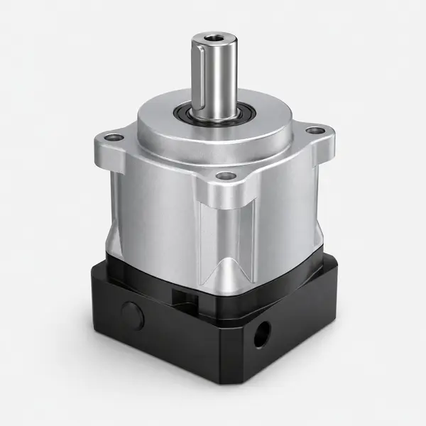
EP-FAB series precision planetary gearbox — J1 base joint for heavy SCARA robots carrying 10kg+ payload where torsional stiffness and P0 backlash are both required

EP-FAB P0 (above) for heavy SCARA J1 where torsional stiffness matters alongside backlash. EP-FAD P0 for standard 3–5 kg SCARA J1/J2. Both share the C1–C10 universal motor adapter system.

01
PCB Component Insertion — High-Speed Electronics Assembly

Electronics assembly SCARA performs 30–60 picks per minute at ±0.05mm TCP over a 300mm × 300mm work envelope. The cycle comprises: Z3 down, J4 orient, pick, Z3 up, J1+J2 reposition, Z3 down, J4 re-orient, place. J1 and J2 execute 30+ direction reversals per minute — a duty profile that accumulates significant backlash wear over the machine’s 5-year production life. Annual cycle count: 30 picks/min × 60 × 20hr/day × 250 days = 9 million picks/year × 5 years = 45 million cycles on J1 and J2. At this cycle count, even EP-FAD P0 at rated S5 duty is within its 30,000hr L10 life — but verify with the actual on-time fraction. EP-FADS P0 at J3 with NYOGEL 792D (ISO Class 5 particle emission) is specified because most electronics assembly lines are ISO Class 6–7 cleanrooms where particle emission from the robot is monitored.

Specification: J1: EP-FAD P0 090mm i=10. J2: EP-FAD P0 060mm i=10. J3: EP-FADS P0 047mm i=5 + 5mm pitch ballscrew. J4: EP-FADS P0 042mm i=5. NYOGEL 792D sealed throughout. IP65 standard.

02
Syringe and Vial Dispensing — Pharmaceutical Assembly

Pharmaceutical SCARA fills syringes and places vials into blister trays under GMP conditions. The Z-axis (J3) depth accuracy is critical — syringe fill depth ±0.1mm determines fill volume accuracy. The gearbox backlash contribution to Z error is: Z_error = (0.78/3438) × 5mm pitch = 0.0011mm — negligible, with the ballscrew preload determining the practical Z accuracy. J1 and J2 TCP accuracy of ±0.1mm for vial-to-tray placement is achievable with P0 at J1 and P1 at J2 (0.118mm calculation above is borderline — for this application, P0 at J2 is specified for margin). GMP environment requires NYOGEL 792D (ISO Class 5 validated) for the sealed lubricant inside the gearbox housing, which does not contact the product. If the robot arm itself is in a Zone 1/2 area (per the Food & Beverage hygienic zone guide), stainless housing and IP69K may be required at J3/J4 which are closest to the product fill path.

Specification: J1: EP-FAD P0 090mm. J2: EP-FAD P0 060mm. J3: EP-FADS P0 047mm. J4: EP-FADS P0 042mm. GMP documentation: per-unit backlash certificate + IP65 test record + NYOGEL 792D ISO Class 5 validation for Annex 1 technical file.

03
Chocolate and Cookie Pick-and-Place — Food Packaging

Food packaging SCARA places chocolate pieces or cookies into trays at up to 80 picks per minute — among the highest SCARA cycle rates in any application. TCP accuracy of ±2mm is generous (product tolerance allows some offset), but the extreme cycle count drives the duty cycle life calculation: 80 picks/min × 60 × 16hr/day × 300 days/yr = 23 million cycles/year. At this rate, even at typical 30% on-time fraction, EP-FAD P0 30,000hr L10 provides approximately 4.1 calendar years (30,000 / (0.30 × 8760) = 11.4 years at full rated torque, but at 30% rated torque: 11.4 × (100/30)³ = 423 years — the gearbox life is not the limit). The real limitation is contamination: food environment requires IP69K and potentially NSF H1 lubricant per the hygienic zone guide. At Zone 3 (outer packaging area), standard IP69K aluminium housing is adequate; for direct product contact areas, stainless + H1 required.

Specification: J1: EP-FAD P1 090mm + IP69K. J2: EP-FAD P1 060mm + IP69K. J3: EP-FADS P1 047mm + IP69K. J4: EP-FADS P1 042mm + IP69K. P1 adequate for ±2mm TCP. Zone per hygienic zone guide.

04
Small Part Press-Fit Assembly — Automotive Components

Automotive SCARA inserts pins, bushings, and bearings into housings with a press-fit Z-axis stroke. TCP accuracy for part location: ±0.1mm XY. Z-depth accuracy: ±0.05mm for correct press-fit depth. The J3 Z-axis is the critical axis for this application — specifically the vertical compliance under press-fit insertion force. During press-fit, the Z-axis motor holds position against the insertion force (typically 50–200N downward) through the gearbox and ballscrew. Any compliance in the J3 gearbox under this reaction torque causes a Z-depth error. Using the compliance formula for J3: Z_error_compliance = (F_insertion × ballscrew_pitch / (2π × Ct_J3)) × arc-min/rad correction. For EP-FADS at Ct ~25 N·m/arc-min: the gearbox compliance contributes approximately 0.003–0.010mm to Z-depth error — well within the ±0.05mm budget. The EP-FAB series is not needed for J3 because the ballscrew preload provides additional holding stiffness. J1/J2 require P0 for ±0.1mm XY placement before the press operation.

Specification: J1: EP-FAD P0 090mm. J2: EP-FAD P0 060mm. J3: EP-FADS P0 047mm (compliance checked). J4: EP-FADS P0/P1 042mm. Industrial environment, no food zone. Standard IP65 sufficient.

05
Liquid Dispensing and Sample Handling — Laboratory Automation

Laboratory SCARA handles microtitre plates, pipettes, and sample tubes in drug discovery and clinical analysis systems. Payload is light (1–2 kg) and speed is moderate (15–30 picks per minute), but accuracy requirements are tight: ±0.2mm TCP for well-to-well placement on 384-well plates (2.25mm well pitch, must land in centre within ±0.1 well width). The SCARA must also provide extremely low particle emission — laboratory environments follow ISO Class 5–6 cleanroom standards for some applications, and any lubrication particles from the gearbox bearings that reach the sample handling area are a contamination event. EP-FADS P0 with NYOGEL 792D sealed (ISO Class 5 validated per the lubricant guide) is the correct specification. For laboratory SCARA handling semiconductor substrates (wafers, glass slides, microtitre plates with precise pitch requirements), the special ratios guide on this site is relevant — specifically the i=21 ratio for 21-slot cassette handlers where the arm must index through integer motor revolutions to eliminate accumulation error at each cassette slot. The same pitch-matching arithmetic from the semiconductor article applies to any SCARA application where the rotary motion must index through a fixed number of positions per full arm rotation. The small payload allows the 047mm FADS frame at J1 and 042mm at J2/J3/J4, keeping the arm very compact and lightweight for the light payloads of lab automation.

Specification: J1: EP-FADS P0 060mm (light payload, small arm). J2: EP-FADS P0 047mm. J3: EP-FADS P0 042mm. J4: EP-FADS P0 042mm. NYOGEL 792D ISO Class 5. No IP69K required for standard lab environment (IP54 minimum sufficient, IP65 for safety margin).

Design Selection

SCARA vs 6-Axis Robot — When the Gearbox Specification Methodology Changes

Korea Ever-Power EP-series gearbox production — manufacturing SCARA robot J1/J2/J3/J4 gearboxes alongside 6-axis robot gearboxes

When to Choose SCARA vs 6-Axis
SCARA:
High-speed horizontal pick-and-place in a fixed Z-stroke envelope
SCARA:
Cycle time <1 second critical; floor space minimal
SCARA:
Application confined to a horizontal plane ±50–200mm Z
6-axis:
Arbitrary 3D path; reach-around obstacles; tilted surfaces
6-axis:
Welding, painting, heavy assembly with complex orientations

The gearbox specification methodology changes significantly between SCARA and 6-axis robots — but the fundamental parameters are the same. What changes is how those parameters are applied. In 6-axis robots, the grade specification at each joint is typically uniform (P0 throughout for precision robots) because the configuration-dependent load variation makes it difficult to calculate which joint can be relaxed without full kinematic simulation. In SCARA robots, the simple two-link planar geometry enables the exact calculation shown in Section 2 above, which often reveals that J2 can be specified one grade looser than J1 without violating the TCP accuracy budget — a cost saving not available in 6-axis robots without the same analytical certainty.

The duty cycle life calculation also differs in emphasis. A 6-axis welding robot runs relatively slow continuous welds — its duty cycle is roughly S1 at moderate torque. A SCARA pick-and-place robot runs extremely fast short cycles — 30–80 picks per minute, each cycle involving acceleration, hold, deceleration across J1 and J2. This produces a high cycle count but a low on-time fraction (each move takes 0.2–0.5 seconds out of a 1–2 second cycle). The S5 duty cycle calculation from the Service Life guide applies directly — and because SCARA picks operate at 20–40% of rated torque (light payloads at high speed), the calculated L10 life at actual operating torque extends to many decades. The practical conclusion: for most SCARA pick-and-place applications, service life is not the limiting design factor when Korea Ever-Power EP-FAD P0 is specified, even at cycle rates of 60+ picks per minute.

📋
SCARA Gearbox Selection Checklist
Before specifying SCARA gearboxes, confirm: (1) TCP accuracy requirement → calculate required J1 grade via δ_J1 = (θ_J1_eff / 3438) × (R1+R2) ≤ 0.7 × TCP_budget. (2) J2 grade → check if P1 is viable via RSS calculation. (3) J3 Z-accuracy → confirm ballscrew pitch and verify gearbox backlash contribution is negligible vs ballscrew preload accuracy. (4) J4 grade → P0 for dispensing/insertion angle accuracy; P1 for general pick-and-place. (5) Cycle count → calculate annual picks, verify S5 L10 life at actual operating torque. (6) Environment → food zone? IP69K? H1 lubricant? Cleanroom? Confirm per hygienic zone guide. (7) Frame size → torque × safety factor 1.5 to select frame. Korea Ever-Power confirms all seven parameters when you provide payload, arm lengths, TCP spec, cycle rate, and environment.

Related EP-Series and Technical Guides
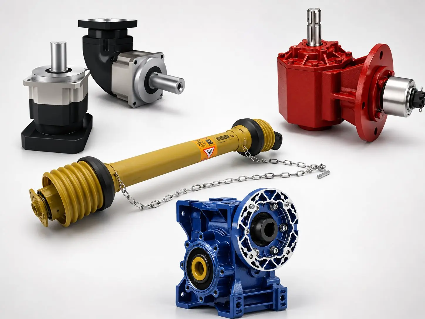
Korea Ever-Power EP series planetary gearbox range — EP-FAD EP-FADS EP-FAB for SCARA robot J1 J2 J3 J4 applications

Browse the full EP catalogue. Companion guides: Industrial Robotics (6-axis), Medical & Lab (cleanroom), Food & Beverage (hygienic zone), and Torsional Stiffness (Ct calculation) on this site. External resources: cvjointdriveshaft.com.

Frequently Asked Questions — SCARA Robot Gearboxes

Can the same EP-FADS frame size be used for both J3 and J4?
Often yes — J3 and J4 can use the same EP-FADS frame size for a standard 3–5 kg payload SCARA, because both joints have relatively light torque requirements (J3 drives a ballscrew, J4 rotates only the tool). The 047mm EP-FADS frame is suitable for both J3 and J4 in many SCARA designs. The key difference is the ratio: J3 typically uses a lower ratio (i=5) to provide adequate motor speed for Z-stroke velocity; J4 may use a higher ratio (i=8–16) for tool orientation resolution and torque amplification. The C1–C10 adapter system allows both to use the same motor model, confirming stock efficiency. For heavier SCARAs where J3 carries a significant press-fit insertion force, the 047mm frame may be undersized for J3 and a 060mm frame should be checked — Korea Ever-Power’s selection tool can confirm for your specific insertion force and Z-stroke speed requirement.
Why is EP-FADS preferred over EP-FAD for SCARA J3 and J4?
Three reasons. First, EP-FADS saves 22mm of axial length by eliminating the adapter plate and external clamp ring between the motor and gearbox — in the compact SCARA wrist assembly where J3 and J4 are stacked axially, this 22mm saving per gearbox is significant for fitting within the wrist envelope. Second, EP-FADS eliminates the small crevice at the adapter plate interface that is present in EP-FAD assemblies — in cleanroom and GMP environments, crevices that can trap particles or lubricant are design non-conformances under EHEDG and GMP guidelines. Third, the direct-insert shaft coupling in EP-FADS provides marginally better concentricity at the motor-gearbox interface than a multi-component adapter system, which is beneficial for the very high input speeds (up to 10,000 rpm) that J4 tool rotation operates at. EP-FAD with the correct C-code adapter is fully acceptable for J3 and J4 where axial space is not a constraint — FADS is preferred only when the wrist envelope is tight or when crevice elimination is a specification requirement.
Is the Z-axis accuracy of a SCARA determined more by the gearbox or the ballscrew?
Primarily the ballscrew, with the gearbox making a small but calculable contribution. For a 5mm pitch ballscrew and EP-FADS P0 (0.78 arc-min backlash): gearbox contribution to Z backlash = (0.78/3438) × 5mm = 0.0011mm. A quality C5-preloaded ballscrew has typical linear backlash of 0.01–0.02mm — ten to twenty times larger than the gearbox contribution. The gearbox backlash is negligible compared to the ballscrew’s own positioning error. For Z-axis accuracy below 0.01mm (which requires a C3-preloaded ballscrew), the gearbox backlash contribution of 0.001mm is still negligible. Therefore: for SCARA J3 Z-accuracy specifications, the ballscrew specification (lead accuracy class, preload class) determines the Z-axis positioning accuracy, not the gearbox grade. EP-FADS P0 provides adequate gearbox performance for all practical SCARA Z-axis accuracy requirements. The gearbox specification for J3 is determined by torque capacity and speed, not by backlash grade. For reference: a C5 rolled ballscrew (standard precision, ±0.023mm/300mm lead accuracy) with double-nut preload (eliminating axial backlash) gives approximately 0.015–0.020mm Z positioning repeatability. A C3 ground ballscrew (precision, ±0.008mm/300mm) with preload gives 0.005–0.008mm Z repeatability. In both cases, the EP-FADS P0 gearbox contribution (0.0011mm) is negligible. Only at very short Z strokes (below 20mm) with extremely tight depth requirements (below 0.002mm) does the gearbox contribution become relevant — and at that point, the appropriate specification upgrade is to a direct-drive Z-axis rather than a gearbox-plus-ballscrew combination.
How does SCARA backlash grow over time, and when should the gearbox be replaced?
SCARA backlash grows through the same mechanism as in 6-axis robots — bearing wear at the output bearings gradually increases the bearing clearance, which manifests as a small increase in the measured backlash at the 2% rated torque test condition. Because EP-FAD P0 units are shipped with a measured backlash stamped on the nameplate (e.g. 0.78 arc-min), the maintenance team has a precise starting value for each joint. At each scheduled maintenance interval (annually, or at every 5 million cycle milestone), measuring the current backlash and comparing to the nameplate value gives the accumulated wear. For a SCARA J1 with ±0.05mm TCP specification, the maximum acceptable backlash (after compensation) is approximately 0.87 arc-min (reverse-calculated from the TCP budget). When the measured backlash reaches 0.87 arc-min, plan a gearbox replacement at the next maintenance window. This condition-based replacement strategy, enabled by Korea Ever-Power’s per-unit nameplate stamping, avoids both premature replacement (wasting the gearbox’s remaining life) and late replacement (allowing TCP accuracy to degrade below specification before the next maintenance visit). For SCARA robots in high-throughput electronics assembly lines, where a TCP accuracy failure causes a production line stop, this predictive maintenance capability is a significant operational benefit.

The predictive maintenance approach enabled by Korea Ever-Power’s nameplate stamping also has implications for spare parts inventory. Because the TCP error budget is known with precision (it is a function of the measured backlash value from the nameplate), the maintenance team can maintain a planned replacement schedule: if the gearbox starts at 0.78 arc-min, and the TCP budget allows up to 0.87 arc-min, the team needs to replace the gearbox when measured backlash reaches approximately 0.85 arc-min — leaving a 2% safety margin. At typical SCARA duty cycles and operating torques, this measured growth happens predictably over 3–7 years of production, giving the team adequate lead time to order a replacement without emergency delivery surcharges. This is a direct contrast to the “replace at fixed interval” approach common with gearboxes that do not provide individual backlash measurements — those replacements may be premature (wasting remaining life) or delayed (allowing hidden accuracy degradation).

Can the EP-series be used in dual-arm SCARA robots?
Yes — dual-arm SCARA (two independent SCARA arms on a shared base or gantry) uses the same gearbox specification as single-arm SCARA, applied independently to each arm. The gearbox selection for each arm follows the same J1–J4 methodology described in this guide, with the arm lengths and payload for that specific arm. The only additional consideration for dual-arm designs is the J1 base joint of the primary arm, which must accommodate the torque from its own arm movement plus any reaction force from the secondary arm if the two arms share a common base rotation. In most dual-arm SCARA designs, the two J1 joints are mechanically independent (each arm has its own J1 motor and gearbox), so no additional loading analysis is needed beyond the single-arm calculation. For configurations where the two arms share a common J1 base, contact Korea Ever-Power with the combined moment loading — the frame size and grade selection for the shared J1 may need to be increased.

Confirm SCARA Gearbox Selection for Your Application
Send your SCARA payload class, upper arm length R1, forearm length R2, TCP accuracy specification, and cycle rate — Korea Ever-Power will confirm the correct EP-series, frame size, and grade for J1 through J4, provide the TCP error budget calculation for J1+J2, and confirm L10 life at your actual duty cycle. Response within one business day.

Confirm SCARA Joint Selection →

Editor: Cxm