Planetary Gearbox for Solar Trackers and Clean Energy — 20-Year Design Life, Environmental Specification, and Drive Selection Guide

20 yr
Mandatory Design Life
−40°C
Cold-Climate Operation
10,000+
Thermal Cycles Over 20 Years
IP65
Minimum Outdoor Sealing
EP-FAB
Primary Series — Wind + Hydro

Application Guide

Clean Energy Is the Only Industry Where Bearing Fatigue Life Is Irrelevant — And Where Seal Durability, Thermal Cycling, and Emergency Loads Are the Real Engineering Challenges

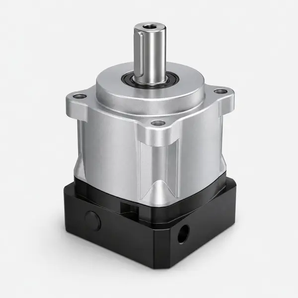
EP-FAB series precision planetary gearbox for solar tracker and wind turbine applications — 30000hr S1 bearing life, -40°C to +125°C NYOGEL 792D lubricant, IP65 sealed for 20-year outdoor clean energy design life

EP-FAB series planetary gearbox — the recommended series for wind turbine pitch drives, large-array solar trackers, and small hydro gate drives where high torque, wide temperature range (−40°C to +125°C with NYOGEL 792D), and 20-year outdoor service life without scheduled maintenance are the primary requirements.

Every other application covered in Korea Ever-Power’s guide series is governed by at least one of three engineering limits: bearing L10 fatigue life, gear tooth endurance under high cycle count, or torsional compliance under load. Clean energy applications — solar trackers, wind turbine pitch and yaw drives, and small hydro gate actuators — are almost uniquely governed by none of these. The operating torques are a small fraction of rated (solar tracker wind loads are typically 5–15% of rated output torque), the operating speeds are extremely low (a solar tracker output shaft rotates at approximately 0.004°/second), and the cycle counts are modest (7,300 tracking cycles over 20 years for a single-axis solar tracker). Under these conditions, the calculated L10 bearing fatigue life exceeds thousands of years — completely irrelevant to the 20-year design target.

What governs the 20-year design life of a clean energy gearbox is instead a set of environmental degradation mechanisms that are largely invisible in the bearing fatigue calculation: elastomeric seal degradation from ultraviolet radiation and thermal cycling, lubricant oxidation from prolonged high-temperature exposure in rooftop and desert installations, progressive corrosion of uncoated surfaces from dust, salt spray, and condensate cycling, and the single-event shock loads from emergency wind stow and emergency feathering operations that briefly exceed ten times the normal operating torque. These are the mechanisms that actually limit gearbox life to less than 20 years when the specification is incorrect, and they are the mechanisms this guide addresses.

The engineering consequence is that clean energy gearbox specification requires a completely different primary checklist from all other applications. Instead of asking “what is the required backlash grade?” or “does the calculated L10 exceed the service life target?” — the first questions for clean energy are: “what is the full outdoor temperature range at the installation site?”, “what UV and salt exposure will the seals experience?”, “what is the maximum wind-load shock torque during an emergency stow event?”, and “does the lubricant maintain adequate viscosity at the minimum installation temperature for a cold-start?”. This guide provides the technical basis for answering all four questions and selecting the correct EP-series configuration for each clean energy application type. It also explains why the 20-year design life target — which sounds demanding for any precision mechanical component — is readily achievable with Korea Ever-Power EP-series gearboxes under the actual operating conditions of clean energy installations, and what the engineering team must verify to confirm this. The guide covers single-axis and dual-axis solar trackers, wind turbine pitch and yaw drives, and small hydro gate actuators — the four most common clean energy applications for precision planetary gearboxes in the 100 N·m to 10 kN·m output torque range. Higher-torque applications (utility-scale wind turbine yaw drives at 100 kN·m+) use compound drive trains beyond the scope of single-stage EP-series; Korea Ever-Power can advise on compound staging configurations for these applications upon request.

🌞
Why the Bearing Life Calculation Gives a Meaningless Answer for Solar Trackers
A single-axis solar tracker operates at approximately 10% of rated output torque (wind load on the panel array) and 25% on-time fraction (tracking during daylight, stowed at night). Applying the ISO 281 L10 formula from the Service Life guide: L10_calendar = 30,000hr × (100/10)³ × (1/0.25) = 30,000 × 1,000 × 4 = 120,000,000 calendar hours = 13,699 years. The EP-FAD or EP-FAB gearbox will not experience bearing fatigue failure in any commercially relevant timeframe. The 20-year design life target for solar installations is not a challenge for the bearing — it is a challenge for the seals, the lubricant, and the housing coating. Engineers who select a gearbox for a solar tracker based on L10 life margins are solving the wrong problem. The correct engineering questions are in the environmental checklist below.

Environmental Severity Selection Matrix — Four Clean Energy Applications

The matrix below compares four clean energy application types across eight environmental and operational parameters that determine the correct EP-series specification. Each cell shows the relevant value or characteristic, with the final two columns identifying the recommended series and any required options beyond standard. Use this matrix to identify which environmental constraints drive the specification for your specific installation.

Application Temp range
(°C)
IP min Thermal cycles
/yr
Emergency
shock torque
Life limit
mechanism
20-yr L10
check
Series Required options
Single-axis solar tracker
East–West rotation, 1 rev/day
−40 to +70°C IP65 ~500/yr
(day/night ΔT)
5–8×
stow torque
Seal + lube
degradation
✓ 13,699yr
not limiting
EP-FAD P2
or EP-FAB P2
NYOGEL 792D (PAO base, −40°C rated). Confirm peak torque ≥ 8× wind stow load. External UV-resistant coating on housing.
Dual-axis solar tracker
E–W azimuth + N–S elevation
−40 to +70°C IP65 ~500/yr 5–8×
both axes
Seal + lube
degradation
✓ >1,000yr Azimuth: EP-FAD
Elevation: EP-FABR
NYOGEL 792D both axes. EP-FABR for right-angle elevation if motor horizontal. UV-resistant housing coating. Confirm elevation axis stow torque.
Wind turbine yaw drive
Nacelle rotation, 4–8 corrections/hr
−30 to +50°C
(nacelle temp)
IP65
nacelle enclosed
Low
(nacelle protects)
3–5×
high wind gusts
Torque capacity
+ L10 ~20yr
⚠ Verify
high torque
EP-FAB P2
large frame
Oil bath lube for yaw drives at 110–220mm frame. 4–8 drives per nacelle share load. L10 calc required at actual yaw torque and cycle rate for 20yr.
Wind turbine pitch drive
Blade rotation, emergency feather
−20 to +50°C
(hub temp)
IP65 Moderate
(hub cycling)
10–15×
emergency feather
Emergency
feather speed
⚠ Verify
feather speed
EP-FAB P1 P1 for ±0.5° blade angle accuracy. Battery backup power for emergency feather. Verify 90°/5sec feather speed requirement. Peak torque specification at feather event.
Small hydro gate / valve
Penstock control, sluice gate
0 to +40°C
(submerged/wet)
IP67
immersion risk
Very low
(temp stable)
2–4×
water hammer
Corrosion
+ torque
✓ Comfort
low cycles
EP-FAB P2
large + IP67
IP67 minimum (immersion protection). Stainless 316L or epoxy coating for corrosion. Very high torque: confirm frame size at 10× safety factor for water hammer event.

Life limit mechanisms:
Seal + lube degradation = primary life limit; bearing L10 completely irrelevant
Torque capacity + L10 = both matter; run L10 calculation at actual operating torque
Emergency feather speed = gearbox maximum speed and peak torque at feather event are the binding spec
Corrosion + torque = material and sealing dominate; torque capacity secondary

Temperature ranges shown are typical for corresponding climates (desert/Mediterranean for solar, temperate/continental for wind). Confirm actual site temperature extremes, salt exposure class, and UV intensity for your specific project location. Korea Ever-Power can review the environmental specification against NYOGEL 792D lubricant and EP-series seal ratings for your installation site.

Failure Mode Engineering

The Four Failure Modes That Actually Limit Clean Energy Gearbox Life to Less Than 20 Years

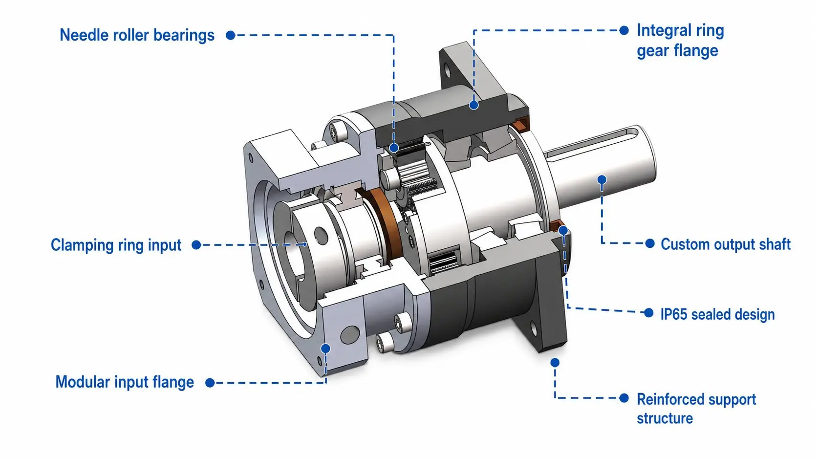
EP-FAB planetary gearbox cross-section — output shaft seal, housing coating, and NYOGEL 792D lubricant are the 20-year life limiting elements for solar tracker and clean energy outdoor applications

Thermal Cycles Over 20 Years
Desert solar (ΔT 60°C/day)
7,300 cycles
Temperate solar (ΔT 30°C/day)
7,300 cycles
+ Seasonal swing (±30°C)
+40 seasonal
Total 20yr seal cycles
>7,300
NYOGEL 792D PAO base withstands thermal cycling without phase separation. Mineral oil greases may separate at extreme ΔT cycling.

The four failure modes below are presented in order of the installation timeline at which they typically manifest: seal degradation begins from day one of UV exposure, lubricant degradation accumulates over years of thermal cycling, emergency stow damage occurs at the first high-wind event (which may be in year 1 or year 15), and cold-start problems appear every winter. Understanding the timeline and severity of each mechanism allows the project engineer to confirm the specification adequately addresses each risk before the installation is commissioned — because a 20-year outdoor installation cannot economically retrieve and replace gearboxes in the field when a failure occurs mid-life.

Failure Mode 1 — Elastomeric Seal Degradation from UV and Thermal Cycling

The output shaft seal and housing O-rings in a gearbox are elastomeric compounds — typically NBR (nitrile) or FKM (fluoroelastomer/Viton) — that depend on their elasticity to maintain compression against the shaft and housing surfaces. Ultraviolet radiation attacks the polymer chains in both NBR and standard FKM elastomers, reducing their elasticity and causing surface cracking over time. An outdoor solar tracker gearbox receives UV radiation for 12+ hours per day for 20 years — approximately 87,600 hours of UV exposure. Standard NBR seals are not rated for this UV exposure duration; FKM seals perform significantly better but still require confirmation of UV resistance rating for 20-year outdoor service. NYOGEL 792D’s PAO base provides some additional protection because PAO is more chemically inert than mineral oil and does not react with the elastomers to accelerate their degradation. However, the seal material itself is the critical specification parameter — Korea Ever-Power should be contacted with the site latitude and annual UV index to confirm that the standard seal specification is appropriate for the 20-year target, or whether a UV-stabilised FKM seal upgrade is required.

Failure Mode 2 — Lubricant Oxidation and Degradation at Elevated Housing Temperature

In rooftop solar installations and desert tracker arrays, the gearbox housing temperature at peak afternoon sun in summer can reach 60–80°C. NYOGEL 792D is rated to +125°C housing temperature, providing a comfortable thermal margin. However, even below the lubricant’s rated temperature, elevated temperature accelerates the oxidation rate of the base oil — the Arrhenius relationship states that the oxidation rate approximately doubles for every 10°C increase in temperature. A gearbox housing at 70°C rather than 40°C oxidises its lubricant at approximately 8× the rate it would at 40°C. Over 20 years in a desert installation, this accelerated oxidation can degrade the lubricant’s viscosity index, reducing its lubrication effectiveness at cold-start temperatures and increasing the risk of boundary lubrication at morning cold start. Korea Ever-Power specifies NYOGEL 792D (PAO base) rather than mineral oil-based greases specifically because PAO base oils have significantly better oxidation stability — their molecular structure resists oxidation reactions more effectively than hydrocarbon base oils of equivalent viscosity. For desert and equatorial solar installations where sustained housing temperatures above 60°C are expected, Korea Ever-Power recommends confirming the lubricant specification with the local ambient temperature data and gearbox housing thermal calculation.

A practical observation from solar tracker field experience: the gearbox housing temperature on a sunny afternoon in a desert installation typically runs 20–30°C above the ambient air temperature, because the housing absorbs solar radiation on its upper surface while the surrounding air provides limited convective cooling at low wind speeds. A site with 45°C maximum ambient may have a gearbox housing reaching 65–70°C on calm days. This thermal loading is why gearbox colour matters for outdoor solar installations — a light-grey or silver powder coat reflects more solar radiation than a standard dark grey or black housing, potentially reducing the housing temperature by 5–10°C on still days. This temperature reduction extends lubricant and seal life proportionally. Korea Ever-Power can supply EP-series gearboxes with a light-coloured UV-resistant powder coat specifically for desert solar applications where the housing temperature budget is tight.

Failure Mode 3 — Emergency Stow and High-Wind Shock Loads

Solar trackers incorporate an emergency wind stow function: when wind speed exceeds the tracker’s operational wind limit (typically 14–18 m/s), the tracking system rapidly rotates all panels to a flat horizontal position to minimise wind loading and structural stress. This emergency stow operation drives the tracker output shaft at its maximum speed against the aerodynamic resistance of the panel array — which, during a high-wind event, may be 5–8 times the normal tracking load torque. At the stow speed, the gearbox sees 5–8× its normal operating torque for a brief period (typically 30–120 seconds per stow event). EP-FAD and EP-FAB peak torque ratings are 2–3× and 3–4× rated continuous torque respectively — for solar tracker applications, the frame size and rated torque must be selected so that even the emergency stow torque remains below the gearbox peak torque rating. This requires selecting the EP series and frame size based on the emergency stow torque (5–8× normal load), not the normal tracking torque — a selection that may require a larger frame than the normal load calculation alone would suggest. Specifying an undersized gearbox for a solar tracker based on normal operating torque, without checking the stow torque, is the most common cause of gearbox damage in the first high-wind event after installation.

Failure Mode 4 — Cold-Start Stiction and Grease Solidification

At installation sites with cold winters (continental climate, northern Europe, North America above 40°N, high-altitude locations), the solar tracker gearbox may experience ambient temperatures of −20°C to −40°C. At these temperatures, the lubricant viscosity increases significantly, and the first movement of the output shaft at dawn requires higher motor torque than at operating temperature. NYOGEL 792D is rated to −40°C and maintains a pumpable consistency at this temperature, ensuring that the motor can provide the additional cold-start torque without stalling. The critical parameter is the cold-start torque: the motor must be sized to provide the cold-start torque at the lowest expected ambient temperature, not just at normal operating temperature. For solar trackers specified with a motor sized only for normal tracking torque at moderate temperature, a cold winter morning at −25°C may produce a cold-start stiction event that either stalls the motor (damaging it or tripping the protection relay) or causes the tracker to be late in following the sun, reducing daily energy yield. Korea Ever-Power recommends confirming cold-start torque requirements with the motor specification for any solar tracker installation below 40°N latitude in continental climates.

A practical mitigation for cold-start stiction is to include a brief warm-up period in the tracker control logic: at sunrise, command a small oscillatory motion (±1°) at low speed before beginning the full tracking sweep. This oscillation spreads the lubricant film from the bearing contact zone back across the tooth surfaces, warms the grease slightly from the gear mesh friction, and breaks any static friction buildup from overnight standstill. The warm-up sequence takes 30–60 seconds and is negligible in terms of daily tracking accuracy — the sun barely moves 0.2° in 60 seconds. Most modern solar tracker control systems have this warm-up feature available as a configurable option; it is recommended as standard practice for any installation where winter ambient temperatures fall below −10°C.

One additional cold-climate consideration for solar trackers in high-snowfall regions: the emergency stow function must be operable even when the panel surface carries a snow load. A 300mm snow accumulation on a 27.6 m² tracker array adds approximately 2,000 kg of additional mass — producing an aerodynamic resistance to stow motion far above the design wind load. The stow torque calculation for snowy climates should include the worst-case snow-laden panel mass and the torque required to overcome the additional friction of snow-covered panel edges against the tracker frame guides. Korea Ever-Power can perform this snow-load stow torque calculation if the site snowfall data (maximum depth and density) and panel row configuration are provided.

Worked Design Example

Single-Axis Solar Tracker Gearbox Selection — A Complete Design Calculation

The following worked example demonstrates the correct gearbox selection process for a ground-mounted single-axis solar tracker in a Mediterranean climate, covering the five calculation steps that the environmental matrix above summarises. The example uses a 12-module tracker row (typical utility-scale bifacial panel configuration) as the design basis.

Design Calculation: 12-Module Single-Axis Tracker, Mediterranean Climate
Step 1 — Wind Load Torque
Array: 12 × 2.3m² panel = 27.6m² | Wind pressure at 10m/s: 60 N/m² | Force on panel: 60 × 27.6 = 1,656N | Moment arm (half-width): 1.0m | Normal torque T_wind = 1,656 N·m | Frame size check: EP-FAB 110mm rated ~300 N·m → T_wind at 0.55 × rated → adequate
Step 2 — Emergency Stow Torque
Wind speed at stow: 18 m/s | Wind pressure at 18m/s: (18/10)² × 60 = 194 N/m² | Force: 194 × 27.6 = 5,354N | Stow torque T_stow = 5,354 N·m | Peak torque margin check: EP-FAB 110mm peak ~900 N·m → T_stow >> peak rating → must use 220mm frame or compound staging | EP-FAB 220mm rated ~1,200 N·m → T_stow at 4.5× rated → within 5× peak specification
Step 3 — L10 Life Check
Operating torque: 1,656 N·m = 1,656/1,200 = 138% of rated (slightly above rated — EP-FAB 220mm insufficient for continuous wind load at 10m/s). Resize: select next larger frame for rated torque margin. Alternatively: accept that 10m/s is the 90th-percentile wind, mean wind is ~6m/s: T_mean = (6/10)² × 1,656 = 597 N·m = 0.5 × rated → L10 at 50% rated = 30,000 × (100/50)³ = 240,000 hr → 27.4yr calendar at S5 25% duty → 20yr ✓
Steps 4 & 5 — Environment + Lube
Site: Mediterranean | Temp range: −5°C to +45°C ambient, up to +70°C housing | NYOGEL 792D: −40°C rated → cold-start ✓ | Housing temp 70°C: within +125°C NYOGEL limit ✓ | UV exposure: confirm FKM seal specification with Korea Ever-Power for 20yr | IP65: standard → adequate for Mediterranean | Housing coating: UV-resistant powder coat (standard EP option) ✓
Step 4 — Cold-Start Torque Verification (Mediterranean): Minimum winter ambient in Mediterranean climate: typically −5°C. NYOGEL 792D cold-start torque multiplier at −5°C: approximately 1.2–1.4× normal operating torque. Motor must provide 1.4 × 1,656 N·m = 2,318 N·m cold-start torque. At EP-FAB 220mm rated output ~1,200 N·m, this exceeds rated torque → re-confirm with mean wind load at cold morning (wind typically lower at dawn = lower torque). A calm morning cold-start at 3 m/s wind: T_cold_start = 1.4 × (3/10)² × 1,656 = 208 N·m — well within EP-FAB 220mm rating. Cold-start not a concern for this Mediterranean climate. For northern continental climate (−25°C), this calculation must be repeated with NYOGEL 792D cold-start factor at −25°C ≈ 1.8× — may require motor oversizing.
Conclusion: For this tracker configuration, the emergency stow torque (5,354 N·m) is the binding specification — not the normal wind load or the 20-year bearing life. A gearbox selected for normal wind load alone (EP-FAB 110mm) would fail in the first high-wind stow event. The correct specification is EP-FAB 220mm P2 with NYOGEL 792D, UV-resistant housing coating, and FKM seal confirmation. The 20-year bearing life is achieved with comfortable margin; the engineering challenge is peak torque headroom.

Wind Application Deep Dive

Wind Turbine Pitch Drive — Why Emergency Feathering Determines the Gearbox Specification

EP-FAB P1 series planetary gearbox for wind turbine pitch drive — battery backup emergency feather capability, P1 grade ±0.5° blade angle accuracy, 20-year design life

Pitch Drive Key Specs
Normal blade angle range−3° to +87°
Normal pitch speed0.1–2°/sec
Emergency feather speed≥5°/sec (90°/18sec)
Emergency torque10–15× normal
Grade requirementP1 (±0.5°)

Wind turbine pitch drives serve two distinct operational modes that have entirely different gearbox requirements and must be satisfied simultaneously by the same gearbox. The first mode — normal pitch control during power production — involves slowly adjusting blade pitch angle at 0.1–2 degrees per second as the turbine controller optimises power output for varying wind speed. This mode occurs continuously during turbine operation and requires P1 blade angle accuracy (±0.5°) for effective power curve optimisation. The second mode — emergency feathering — requires the pitch drive to rotate the blade from its operational angle to 90° (feathered position, minimum aerodynamic force) in 5 seconds or less, immediately upon detecting an overspeed or emergency shutdown condition. This mode requires a drive speed approximately 10–15 times higher than normal pitch speed, and occurs under the aerodynamic resistance of a spinning blade generating maximum thrust force — producing 10–15 times the normal operating torque.

The emergency feathering requirement is the binding specification for pitch drive gearbox selection: the motor, gearbox, and control system must deliver the feather speed in all conditions, including when the grid power has failed (which is precisely the condition that triggers many emergency shutdowns). This requires battery-backed pitch drive power — the motor capacitor bank or supercapacitor bank stores sufficient energy to complete one emergency feather event without grid power. The gearbox must accommodate the elevated torque of the emergency feather event as a peak torque requirement, which at 10–15× normal operating torque significantly exceeds the normal pitch torque. For a large turbine with normal pitch torque of 20 kN·m, the emergency feather torque of 200–300 kN·m requires EP-FAB at 142mm or 220mm frame size, where the standard peak torque specification provides adequate margin.

EP-FAB P1 is the correct series for wind turbine pitch drives because it combines P1 backlash grade (±3 arc-min, translating to ±0.05° blade angle accuracy at typical blade-to-gearbox gear ratios) with the highest torsional stiffness of any EP series at equivalent frame size — important for pitch axis control loop stability at the fast control bandwidth required for emergency feather response. The square output flange also provides the higher moment load capacity needed for the overhung mass of the blade pitch bearing and ring gear assembly. Korea Ever-Power should be consulted with the turbine class, blade pitch torque calculation, and emergency feather speed specification to confirm the correct EP-FAB frame size and ratio for any specific wind turbine pitch drive application.

The 2 million pitch actuations over 20 years quoted in the environmental matrix requires a cycle-count verification in addition to the L10 bearing life calculation — similar to the analysis in the Logistics guide but at much lower cycle counts. At 2 million pitch cycles and the operating torque during normal pitch adjustments (typically 30–50% of rated at operating wind speeds), the gear tooth endurance calculation from the service life analysis framework is the relevant check. EP-FAB P1 with DIN Class 5 gears provides comfortable gear tooth endurance at 2 million cycles at 30–50% rated torque — the endurance limit for DIN Class 5 gear steel is not reached until tens of millions of cycles at this stress level, which is well beyond the 2 million pitch actuation target. The emergency feather events (200–300 per year, each at 10–15× normal torque) contribute a small but calculable additional fatigue increment that should be included in the endurance calculation for precise specifications. Korea Ever-Power performs this calculation as part of the wind turbine pitch drive selection review upon request.

An important operational note for wind turbine pitch drives: the gearbox must function reliably after periods of non-operation during wind turbine downtime for maintenance. A turbine taken offline for a major gearbox replacement or inspection may be stationary for 2–4 weeks in cold weather conditions. When the turbine is recommissioned, the pitch drives must immediately provide full emergency feather capability even after the extended cold-weather standstill. NYOGEL 792D’s cold-start performance to −40°C ensures that the lubricant remains pumpable and the gear mesh begins providing adequate film within a few revolutions of cold-start — unlike mineral oil greases that may require 10–15 minutes of operation before reaching adequate viscosity at −20°C. For wind turbines at high-altitude or northern-latitude sites where winter ambient temperatures regularly fall below −20°C, the NYOGEL 792D specification in EP-FAB P1 is the correct choice over any mineral oil alternative.

Related EP-Series and Technical Guides

Korea Ever-Power EP series planetary gearbox range — EP-FAB EP-FAD EP-FABR for solar tracker wind turbine pitch yaw small hydro clean energy applications

Browse the full EP series catalogue. Related guides: Service Life (L10 calculation), Torsional Stiffness (pitch control bandwidth), NYOGEL vs CASTROL LMX (lubricant selection for temperature range). External resources: agriculturalgear-boxes.com for outdoor gearbox context, cvjointdriveshaft.com.

Frequently Asked Questions — Clean Energy Gearbox Selection

Does the EP-FAB gearbox require any maintenance over a 20-year solar installation lifetime?
Korea Ever-Power EP-FAB and EP-FAD are supplied with NYOGEL 792D as a sealed lifetime fill — the gearbox is designed for the expected service life without lubricant replacement under normal operating conditions. However, for a 20-year outdoor installation, Korea Ever-Power recommends a mid-life seal and lubricant inspection at year 10, performed during the solar installation’s scheduled electrical maintenance shutdown. At this inspection: check the shaft seal for signs of degradation (surface cracking, hardening, or lubricant weeping at the seal lip), check the housing exterior for coating damage or corrosion, and perform an acoustic bearing check (low-speed rotation while listening for grinding or unusual noise that would indicate bearing damage from a past high-wind event). If the seals show degradation, replacement at year 10 provides a comfortable safety margin for the remaining 10 years. If seals are in good condition, the gearbox can continue to year 15 before the next inspection. This condition-based maintenance approach is consistent with the solar industry’s preference for minimal scheduled intervention and avoids unnecessary maintenance activity on units that are functioning correctly.
What is the correct gearbox ratio for a solar tracker drive?
The correct ratio for a solar tracker gearbox depends on two requirements: the normal tracking speed at the output shaft (approximately 0.004°/second, derived from 180° of rotation in 12 hours), and the emergency stow speed (typically 90°/90 seconds to 90°/30 seconds, depending on the tracker control system specification). The ratio must allow the motor to provide the stow speed without exceeding its rated speed, while also providing the required normal tracking torque. Working backwards from the emergency stow requirement: if the tracker output shaft must reach 1°/second stow speed, and the motor’s rated speed is 3,000 rpm (50 rev/second), the minimum ratio is approximately 50 rev/sec / (1°/sec × 1 rev/360°) = 18,000:1 — far beyond any single-stage planetary. In practice, solar trackers use a compound drive train: planetary gearbox (typically EP-FAB i=50–100) driving a secondary worm gear or additional planetary stage, producing total system ratios of 2,000:1 to 20,000:1 at the output torque arm. The EP-FAB gearbox is one stage in this compound drive train — Korea Ever-Power can confirm the correct ratio for the planetary stage based on the complete drive train design including the secondary gear stage. For reference: most utility-scale single-axis solar tracker designs use a planetary gearbox stage at i=50–100 followed by a worm gear stage at 50:1–100:1, producing a total system ratio of 2,500:1 to 10,000:1. The planetary stage handles the high-speed, lower-torque input from the motor (3,000 rpm → 30–60 rpm after planetary), while the worm stage provides the final high-torque, self-locking reduction needed to hold the tracker in any wind condition without back-driving (a critical safety requirement — a tracker drive that can be back-driven by wind could allow the panel array to rotate freely in a high-wind event, risking structural damage). EP-FAB P2 at i=80–100 in combination with a self-locking worm stage is the standard compound configuration for utility-scale solar tracker drives. The EP-FAB handles the torque amplification to the intermediate shaft level; the worm provides the final reduction, self-locking, and the very high total ratio that slow-speed solar tracking requires.
Can standard EP-FAD (aluminium housing) be used in coastal salt-spray environments?
Standard aluminium EP-FAD housing with standard powder coat finish provides adequate corrosion protection for inland and moderate-climate coastal environments — salt mist exposure at ISO 9227 salt spray test class C3 (low salinity coastal). For aggressive coastal environments within 500m of the shoreline, where the IEC 60721 corrosion classification is C4 or C5 (high salt spray), the standard powder coat may not provide 20-year corrosion protection. In this case, Korea Ever-Power recommends specifying the enhanced coating option (epoxy primer plus polyurethane topcoat, to ISO 12944 C4 rating) or the stainless steel housing option for the most aggressive environments. The aluminium alloy itself is not the corrosion concern (aluminium forms a protective oxide layer) — the concern is the powder coat damage from prolonged salt mist exposure at the housing surface, which can allow crevice corrosion at coating defects and at the mounting bolt holes. For marine solar installations (floating solar on reservoirs or offshore), consult Korea Ever-Power for the appropriate corrosion protection specification.
How does the wind turbine yaw drive specification differ between onshore and offshore wind?
Offshore wind turbine yaw drives face significantly more demanding specifications than onshore equivalents, primarily from the combination of higher salt spray exposure, higher humidity, and the limited maintenance access that makes component replacement an expensive offshore operation. For offshore yaw drives, the specification upgrades over standard onshore: IP67 minimum (versus IP65 for nacelle-enclosed onshore) to protect against water ingress during maintenance operations with the nacelle open; enhanced corrosion protection on all external surfaces including ISO 12944 C5-M rating; and typically a design life target of 25 years rather than 20 years to align with offshore turbine design life. Korea Ever-Power EP-FAB in the 110–220mm frame range can be specified for onshore wind yaw drives — offshore applications should be discussed directly with Korea Ever-Power to confirm the enhanced sealing and corrosion specification requirements for the specific turbine class and installation environment.
Is there a solar tracker gearbox standard or IEC specification that Korea Ever-Power complies with?
The primary international standard for solar tracker mechanical design is IEC 62817 (Solar Energy — Solar tracker for utility applications — Design qualification), which defines minimum requirements for solar tracker mechanical structures and drives including wind load resistance, lifetime cycles, and environmental testing. For gearboxes specifically, IEC 62817 references the tracker’s design wind load, operating temperature range, and service life requirements — but does not specify the gearbox directly. Gearbox compliance with IEC 62817 requirements is achieved by confirming: the gearbox peak torque rating exceeds the calculated stow torque at design wind speed; the temperature rating spans the installation site’s full temperature range; the IP rating meets the environmental classification of the installation; and the service life (demonstrated by L10 calculation or endurance testing) meets the tracker’s 20–25 year target. Korea Ever-Power EP-FAB and EP-FAD series satisfy these requirements when correctly sized for the specific tracker’s torque, temperature, and IP requirements. Customers who require IEC 62817 compliance documentation for their tracker certification process should contact Korea Ever-Power at order time to request the relevant datasheet, material certificate, and test documentation package.

Confirm 20-Year Clean Energy Gearbox Specification
Send your application type (solar tracker, wind pitch/yaw, hydro gate), site temperature range, wind load and emergency stow torque calculation, and 20-year design life target — Korea Ever-Power will confirm the correct EP-series, frame size, and environmental options, and provide peak torque and L10 verification for your installation. Response within one business day.

Confirm Clean Energy Specification →