Planetary Gearbox Torsional Stiffness — How Ct (N·m/arc-min) Affects Positioning Accuracy Under Load

Ct
Torsional Stiffness Symbol
N·m/arc-min
Stiffness Units
FAB > FAD
Square > Round Flange
≠ Backlash
Different Error — Different Fix
δ = T/Ct
Compliance Error Formula

Engineering Fundamentals

Torsional Stiffness — The Specification That Backlash Cannot Fix and That Most Engineers Discover Too Late
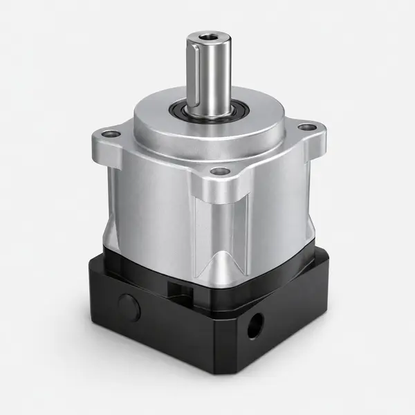
EP-FAB series high precision planetary gearbox — square flange design provides higher torsional stiffness Ct than round-flange EP-FAD at same frame size for CNC rotary table and high-stiffness applications

EP-FAB series — square output flange. The wider bearing span and larger output shaft diameter of the square-flange design produce significantly higher torsional stiffness Ct than the round-flange EP-FAD at the same frame size. For CNC rotary tables, telescope drives, and press brake axes where load-proportional deflection is the error source, FAB is the correct specification regardless of backlash grade.

Torsional stiffness (symbol Ct, units N·m/arc-min) is the ratio of applied torque to the resulting angular deflection at the output shaft. A gearbox with Ct = 40 N·m/arc-min will deflect its output shaft by 1 arc-minute when a torque of 40 N·m is applied. A gearbox with Ct = 10 N·m/arc-min will deflect 4 arc-minutes under the same torque. This deflection — called compliance error, or sometimes spring-back error — appears as a positional inaccuracy that is directly proportional to the applied load.

Torsional stiffness is the second most-specified parameter in precision gearbox procurement, after backlash grade. Yet in twenty articles of Korea Ever-Power’s engineering guide series, it has not been fully explained — because the guide series focused on applications and product features first, and the two parameters that drive the majority of application problems (backlash and service life) were addressed in dedicated guides. This guide closes that gap. It presents torsional stiffness alongside backlash grade as a co-equal specification parameter — not a secondary consideration. For the applications where load-proportional deflection is the dominant positioning error source (CNC rotary tables, press brakes, telescope drives, heavy-payload robot joints), specifying torsional stiffness correctly is as important as specifying backlash grade — and the two specifications address completely independent error mechanisms. A gearbox perfectly specified for backlash grade but with insufficient Ct will still show unacceptable positional error under load, regardless of how well the servo backlash compensation is tuned.

The torsional stiffness of a planetary gearbox has multiple contributing mechanisms, each of which can be the dominant term depending on the loading condition. The gear mesh stiffness (the resistance to rotation created by the contact stiffness of the meshing teeth) is the component that most engineers think of first — but for precision gearboxes with DIN Class 5 helical gears, the gear mesh stiffness is very high and rarely the limiting term. The dominant torsional compliance mechanisms in a well-designed planetary gearbox are the output bearing pair’s resistance to moment loads (angular deflection of the output shaft due to combined torque and radial load at the flange), the torsional compliance of the output shaft itself (proportional to shaft length³ and inversely proportional to diameter⁴), and the structural compliance of the housing under the reaction forces from the gear mesh. Of these, the output bearing moment stiffness is typically the largest compliance contributor — which explains why EP-FAB, with its wider bearing span, achieves significantly higher Ct than EP-FAD at the same frame size despite using the same gear train.

The critical distinction that this guide establishes is: backlash error and compliance error are fundamentally different in nature, have different causes, and require different solutions. Backlash error is a direction-reversal dead zone — it occurs when the drive reverses direction and can be addressed by servo backlash compensation. Compliance error is a load-proportional angular deflection — it is present whenever torque is applied to the output shaft, in both directions of rotation, and it cannot be compensated by servo backlash compensation because it is not a dead zone. A machine that has excellent backlash grade (P0, 0.78 arc-min) but insufficient torsional stiffness will show positioning errors that persist even with perfectly tuned servo compensation — because those errors are not from backlash but from gear train deflection under load.

💡
The Most Important Insight in This Guide
Backlash compensation in the servo controller corrects for the angular dead zone at direction reversal. It has no effect on load-proportional deflection. If you improve a gearbox from P1 to P0 grade and the machine’s positional error remains the same under load, the problem is torsional compliance, not backlash — and the correct solution is to specify a stiffer series (EP-FAB instead of EP-FAD) or a larger frame size, not a tighter backlash grade. Conversely, if the positional error occurs specifically at direction reversals and disappears at constant velocity, the problem is backlash — and improving backlash grade is the correct solution. Diagnosing which error type you have determines which specification to change.

EP-Series Torsional Stiffness Comparison — 090mm Frame, All Series

The chart below shows indicative torsional stiffness Ct values for all EP-series at the 090mm frame size, with application requirement reference lines. Series to the right of an application’s reference line are stiff enough for that application; series to the left are not. The application lines show the minimum Ct needed to keep load-proportional compliance error below the application’s positional tolerance.

Values shown are indicative engineering estimates based on typical output bearing span, shaft diameter, and gear mesh compliance for each series at 090mm frame. Actual Ct values depend on ratio, load direction, and bearing preload. Request confirmed Ct values from Korea Ever-Power for specification-critical applications.

Ct (N·m/arc-min) →
090mm frame, typical rated torque range

10
20
30
40
50
60
70
80+

EP-FAB P0
Square flange
~45 N·m/arc-min

EP-FABR
Square R/A
~40 N·m/arc-min

← CNC 5-axis / press brake minimum (Ct ≥ 40)

EP-FAD P0
Round inline
~28 N·m/arc-min

EP-FADR
Round R/A
~24 N·m/arc-min

← Robot J1/J2 minimum (Ct ≥ 20)

EP-FADS
Direct insert
~25 N·m/arc-min

EP-FAL
Belt-pulley
~22 N·m/arc-min*

← Conveyor / AMR minimum (Ct ≥ 5)

EP-FPG
Economy round
~8 N·m/arc-min

01020304050607080 N·m/arc-min

EP-FAB/FABR — highest stiffness, square flange design

EP-FAD/FADR/FADS — medium stiffness, round flange

EP-FAL — medium*, belt compliance adds to system compliance

EP-FPG — economy, lower stiffness; adequate for non-precision drives

*FAL stiffness at gearbox output; total system compliance includes belt stretch separately

Application reference lines show minimum Ct needed to keep compliance error below ±0.5 arc-min for CNC 5-axis (at 35 N·m typical cutting torque), ±1 arc-min for robot J1/J2 (at 80 N·m rated joint torque), and ±5 arc-min for conveyor (at 20 N·m typical drive torque). Calculated using δ = T / Ct where δ is allowable compliance error. Larger frame sizes (110mm, 142mm) provide proportionally higher Ct.

Calculation Method

How to Calculate Compliance Error and Whether Your Application Needs a Stiffer Series

EP-FAB series planetary gearbox — square output flange cross-section showing wider bearing span and larger output shaft that produces higher torsional stiffness than EP-FAD round flange

Compliance Error Formula
δ (arc-min) = T ÷ Ct
δ = angular compliance error (arc-min)
T = applied torque at gearbox output (N·m)
Ct = torsional stiffness (N·m/arc-min)
Example: T = 35 N·m, Ct = 28 N·m/arc-min
δ = 35 ÷ 28 = 1.25 arc-min compliance error

The Three-Step Compliance Error Assessment

The compliance error formula δ = T/Ct is the gearbox equivalent of the backlash grade selection formula introduced in the grade selection guide. Just as θ = (δ/r) × 3438 tells you what backlash grade is needed for a given linear accuracy requirement, δ = T/Ct tells you what minimum torsional stiffness Ct is needed to keep load-proportional compliance error below your accuracy budget. The two formulas address different error sources that both contribute to the total positional error of a servo axis.

  1. 1
    Identify the maximum torque at the gearbox output during the precision phase

    This is the torque that causes the compliance error you are concerned about — typically the cutting force torque for a CNC rotary table, the payload gravity torque for a robot joint, or the bending force torque for a press brake back-gauge. It is not necessarily the rated torque or the peak torque — it is the torque that is applied at the moment the machine is making a precision measurement or maintaining a precise position. Calculate this from your application’s force or moment requirements, not from the gearbox torque rating.

  2. 2
    Determine the allowable compliance error for your accuracy specification

    Convert your linear positional accuracy specification to arc-minutes using the same formula from the grade selection guide: θ (arc-min) = (δ_linear / r) × 3438, where r is the radius from the gearbox output shaft to the accuracy measurement point. This is your total positional error budget. Subtract the backlash contribution (from the grade selection calculation) to get the remaining budget available for compliance error. The compliance error budget = total error budget − backlash contribution.

  3. 3
    Calculate minimum required Ct = T ÷ compliance_error_budget

    Rearranging the compliance formula: Ct_min = T / δ_compliance_budget. Compare this to the Ct values in the bar chart above for the relevant frame size. Select a series whose Ct exceeds Ct_min. If EP-FAD at the required frame size has insufficient Ct, step up to EP-FAB at the same frame size (which provides higher Ct without changing the mounting dimensions). If EP-FAB at the same frame size still has insufficient Ct, use the next larger frame size.

🔧
Stiffness Upgrade Without Frame Change: FAD → FAB
If your compliance calculation shows that EP-FAD at your required frame size is insufficient, the first step is to check EP-FAB at the same frame size. EP-FAB and EP-FAD share the same gearbox body dimensions at each frame size — the output shaft diameter, mounting bolt pattern, and gearbox envelope are compatible. Upgrading from EP-FAD to EP-FAB for a stiffness-driven requirement is a direct swap of the gearbox unit without any changes to motor, mounting hardware, or downstream coupling. The C1–C10 motor adapter (for FAD→FAB upgrade) remains the same. EP-FAB P0 at 090mm provides approximately 1.6× higher Ct than EP-FAD P0 at 090mm — a meaningful stiffness improvement at a modest price premium and with no mechanical redesign.

Worked Example: CNC 5-Axis B-Axis at 315mm Rotary Table
Application Parameters
Table radius: 315mm | Linear accuracy spec: ±0.05mm | Max cutting torque: 35 N·m | Backlash budget: 0.78 arc-min (EP-FAD P0 with compensation)
Calculation
Total budget: (0.05/315) × 3438 = 0.546 arc-min | After backlash (0.78 × 0.4 = 0.31 with comp.): compliance budget = 0.546 − 0.31 = 0.236 arc-min | Ct_min = 35 / 0.236 = 148 N·m/arc-min
Result
Ct_min = 148 N·m/arc-min — significantly above EP-FAB 090 (~45) or even 110 (~85). This application needs a 142mm or 180mm frame EP-FAB, or an additional outboard bearing support for the rotary table. Confirms why CNC 5-axis rotary tables use dedicated indexing tables with integrated high-stiffness bearings, not standard planetary gearboxes alone.

Design Engineering

Why EP-FAB Is Stiffer Than EP-FAD at the Same Frame Size — Four Structural Differences
Planetary gearbox types comparison — EP-FAB square flange vs EP-FAD round flange structural difference showing wider output bearing span for higher torsional stiffness

Output Interface Comparison
EP-FAB Square Flange
Wide 4-bolt square flange | Large-diameter output shaft | Extended bearing housing spans | High moment load capacity | Ct ~45 N·m/arc-min at 090
EP-FAD Round Flange
Compact round flange | Standard output shaft diameter | Shorter bearing housing | Good moment load | Ct ~28 N·m/arc-min at 090
FAB Ct / FAD Ct ≈ 1.6× at same frame size (090mm)

The torsional stiffness difference between EP-FAB (square flange) and EP-FAD (round flange) at the same frame size — approximately 1.5–1.8× higher Ct for FAB — arises from four structural design differences. Each contributes independently to the stiffness improvement, and together they explain why the square-flange series exists as a separate product: not for a different gear accuracy or backlash capability, but for a fundamentally stiffer output interface.

  1. 1.
    Wider output bearing span

    The square flange of EP-FAB allows a larger output housing that accommodates two output bearings with a wider separation distance (axial span). The torsional stiffness contribution from the output bearings scales approximately with the square of the bearing span — doubling the span roughly quadruples the bearing pair’s resistance to moment loading. EP-FAB’s wider bearing span is the single largest contributor to its higher Ct versus EP-FAD at the same frame size.

  2. 2.
    Larger output shaft diameter

    The square flange design allows a larger-diameter output shaft than the round flange format at the same frame size. Torsional stiffness of a shaft scales as the fourth power of its diameter — a 10% increase in shaft diameter produces a 46% increase in shaft torsional stiffness. EP-FAB’s larger output shaft diameter provides a meaningful contribution to the total Ct advantage over EP-FAD.

  3. 3.
    Stiffer mounting interface

    The four-bolt square flange pattern distributes the mounting reaction forces over a wider area and a more symmetric bolt pattern than the round flange. Under combined torque and overhung moment loading (which is the typical loading condition in CNC rotary tables and press brake drives), the square flange provides a more rigid attachment to the machine structure — reducing the structural compliance contribution to the total Ct measurement.

  4. 4.
    Gear mesh stiffness is the same — it is not the differentiator

    A common misconception is that EP-FAB has stiffer gears than EP-FAD — it does not. Both series use DIN Class 5 profile-ground helical gears with the same gear mesh stiffness for equivalent module and face width. The torsional compliance of the gear mesh itself is nearly identical between FAB and FAD at the same frame size. The FAB Ct advantage comes entirely from the structural differences at the output interface (bearing span, shaft diameter, mounting geometry) — not from the gear train.

Error Diagnosis

Diagnosing Your Positional Error — Backlash or Compliance, and What to Specify

The most useful diagnostic tool for a servo axis with unexplained positional error is a simple motion test that distinguishes backlash error from compliance error. The two error types produce different signatures in the position trace that can be identified without specialist equipment — a servo drive with position display and a light probe or indicator mounted on the output axis is sufficient.

Error Characteristic Backlash Error Compliance Error Diagnosis action
When it appears Only at direction reversals; disappears during constant-velocity motion Present whenever torque is applied; proportional to load magnitude; appears in both directions Move at constant velocity while monitoring position; apply load at constant position
Error magnitude vs load Fixed magnitude (=backlash value); does not change with load level Proportional to applied torque; doubles when load doubles Hold at constant position; apply known torque; measure angular shift. If shift ∝ torque → compliance
Effect of servo compensation Reduced by 60–70% with compensation; effectively eliminated at P0 grade with good tuning No effect from servo backlash compensation; compliance error is load-proportional, not a dead zone Enable servo compensation; re-measure. If error persists → compliance. If reduced → backlash.
Correct solution Tighter backlash grade (P1→P0) or better servo compensation calibration Higher Ct: upgrade to FAB (same frame, 1.6× stiffer) or larger frame size; external outboard bearing support Calculate Ct_min = T / δ_compliance_budget. If current series Ct < Ct_min → specify FAB or larger frame
Wrong solution Upgrading to FAB for backlash-only problem adds cost with no benefit; P0 compensation solves it Upgrading from P1 to P0 grade for compliance-only problem adds cost with no benefit; Ct is the issue Misdiagnosis wastes budget. Run the diagnostic test before specifying a solution.

📐
The Complete Positional Error Budget — All Three Components
A precision servo axis has three independent error sources that sum in the positional error budget: (1) Backlash error: δ_bl = (backlash × 0.4) / 3438 × r [mm] — direction reversal dead zone, reducible by grade and compensation. (2) Compliance error: δ_comp = (T / Ct) / 3438 × r [mm] — load-proportional deflection, reducible only by higher Ct. (3) Encoder/control error: δ_enc = encoder_resolution / (i × 3438) × r [mm] — reducible by higher encoder resolution or lower ratio. The total error is approximately √(δ_bl² + δ_comp² + δ_enc²) (RSS sum, assuming independent sources). For the majority of precision servo applications, backlash and compliance are the dominant terms and encoder error is negligible at modern 17-23 bit encoder resolutions. Specify the grade (backlash) and series (Ct) together to balance both error contributions within the total error budget.

The Practical Field Measurement — How to Distinguish Backlash from Compliance in 10 Minutes

With a dial indicator or laser displacement sensor mounted on the output axis, and a means of applying a known torque load at the output (either a calibrated weight at a known radius, or a torque wrench against a fixed stop), the following procedure distinguishes backlash error from compliance error in a single test session.

Zero the indicator at a reference position. Move the axis to a reference position at constant velocity (no direction reversal). Record the indicator reading. This establishes a baseline with no backlash dead zone and no applied external load.
Apply a known clockwise torque load. Apply approximately 20% of rated output torque clockwise through the calibrated weight or torque wrench. Record the indicator displacement from baseline. This reading is the compliance error at 20% rated torque. If it is non-zero, compliance error exists.
Apply 50% of rated torque. If the indicator displacement scales proportionally (approximately 2.5× the 20% reading), the error is compliance-dominated. If it does not scale proportionally, there may be a non-linear stiffness effect or a mixed backlash/compliance contribution.
Remove the load and perform a direction reversal. Move the axis a small amount clockwise then counterclockwise under servo control with no external load. The position error at the reversal point, compared to the commanded position, is the backlash dead zone. If this equals the grade specification (≤3 arc-min for P1, ≤1 arc-min for P0), backlash is within specification. If the reversal error greatly exceeds the compliance error from steps ②–③, backlash is the dominant error source.

This four-step test takes approximately 10 minutes with basic metrology equipment and provides the diagnostic data needed to decide whether backlash grade upgrade, series upgrade, or both is required. The result maps directly to the specification action: compliance-dominated error → upgrade series or frame size; backlash-dominated error → upgrade grade or improve compensation tuning; both → upgrade both grade and series.

A useful cross-check after running the diagnostic test is to compare the measured compliance error with the value predicted by the formula δ = T/Ct using the Ct from the bar chart. If the measured compliance closely matches the prediction, the compliance mechanism is as modelled (primarily gear mesh and bearing compliance) and the specification upgrade path is clear. If the measured compliance is significantly higher than predicted, additional compliance sources are present — typically the machine structure’s flexibility at the gearbox mounting, the coupling between the gearbox and the load, or backlash in a secondary drive element (leadscrew nut, rack-and-pinion, or coupling jaw). In that case, upgrading the gearbox Ct alone may not solve the compliance problem — the structural compliance must also be addressed. Korea Ever-Power can assist with this analysis when the diagnostic test results are provided.

One more practical scenario worth covering is the mixed case: a machine that shows positional error from both backlash and compliance simultaneously. This is common in older machines where the gearbox has accumulated backlash growth over service life (increasing the backlash contribution) while the machine structure has also become slightly compliant through wear and loosening of structural fasteners. In this mixed case, upgrading the gearbox alone (whether for grade or stiffness) will not solve the problem — the structural compliance must also be addressed. The diagnostic test above separates the two contributions so the engineer can quantify each and decide whether one or both require remediation.

Application Examples

Five Application Examples — When Torsional Stiffness Determines the Series Selection

1
CNC 5-Axis Machine Tool B-Axis Rotary Table — FAB Required

Titanium milling at 35 N·m cutting torque, ±0.05mm positional accuracy at 315mm table radius. Using the compliance formula: required Ct_min = 35 / [(0.546 arc-min total budget − 0.31 arc-min backlash) × 1 arc-min/N·m] = 148 N·m/arc-min. This exceeds all standard planetary gearbox Ct values — the correct solution for this application is a dedicated CNC tilting rotary table with integrated cross-roller bearings providing Ct > 400 N·m/arc-min, with the EP-FAB gearbox driving the rotary table through a reduction. The gearbox alone is not the stiffness element in this configuration — the table structure provides the stiffness.

Lesson: For the highest-stiffness CNC applications, the gearbox drives a precision table structure — the gearbox Ct contributes to but does not solely determine the system stiffness. Specify EP-FAB P0 for the drive gearbox; specify the table for the stiffness requirement.
2
Press Brake Back-Gauge X-Axis — FAB Preferred Over FAD

Back-gauge positions the workpiece for bending; bending force creates torque on the back-gauge drive during the bend stroke. At a typical back-gauge torque of 25 N·m and ±0.1mm positional accuracy requirement with a 50mm leadscrew equivalent radius: compliance budget = (0.1/50 × 3438) − backlash = 6.87 − (2.5 × 0.4) = 5.87 arc-min. Required Ct_min = 25/5.87 = 4.3 N·m/arc-min. Both EP-FAD and EP-FAB easily exceed this — FAD P1 (Ct ~28) is adequate. However, EP-FAB P1 is specified because the back-gauge’s overhung load (weight of the gauge plate at the end of the leadscrew) also contributes to compliance at the gearbox output. FAB’s stiffer output interface reduces the overhung load compliance contribution beyond what the formula above captures.

Lesson: When overhung loads are significant alongside the torque load, FAB’s structural stiffness advantage is worth the modest cost premium over FAD even when the pure torque calculation shows FAD is adequate.
3
Robot J2 Shoulder Joint at 10kg Payload — FAD Is Adequate

Robot J2 shoulder with 10kg payload at 600mm reach: gravity torque at J2 = 10 × 9.81 × 0.6 = 58.9 N·m at full extension. TCP accuracy spec ±0.1mm. At the J2 gearbox (400mm from TCP to J2 centre): compliance budget = (0.1/400 × 3438) − (0.78 × 0.4) = 0.859 − 0.312 = 0.547 arc-min. Required Ct_min = 58.9 / 0.547 = 107 N·m/arc-min. This exceeds EP-FAD 090 (~28) — but the J2 gearbox for this payload class is typically a 110mm or 142mm frame, where EP-FAD Ct is proportionally higher (~55 for 110mm). At 110mm EP-FAD: Ct ~55, compliance error = 58.9/55 = 1.07 arc-min — over budget. Upgrade to EP-FAB 110mm (Ct ~85): compliance error = 58.9/85 = 0.69 arc-min — still slightly over budget. Conclusion: for high-payload robot J2, combined grade selection + stiffness analysis is needed; EP-FAB 142mm or TCP compliance budget must include the structural flexibility of the arm, not just the gearbox.

Lesson: Robot TCP accuracy budgets must include compliance contributions from all joints and from the arm structure, not just the gearbox. Gearbox Ct is one element of the total compliance budget.
4
AGV Drive Wheel — Stiffness Is Irrelevant

AGV traction drive at 100 N·m rated torque and ±2mm stop accuracy: compliance budget = (2/75 × 3438) × arc-min/mm − ignore, because the AGV stop accuracy is dominated by inertia and encoder resolution, not gearbox compliance. Even at EP-FPG Ct ~8 N·m/arc-min: compliance error = 100/8 = 12.5 arc-min = 0.163 mm at 75mm wheel radius. This is well within the ±2mm stop accuracy budget. Torsional stiffness is completely irrelevant to the AGV selection — choose EP-FPG for efficiency (≥97%) and cost, not for Ct.

Lesson: Do not specify high-stiffness gearboxes for applications where compliance error is not in the positional error budget. AGV, conveyor, and transport drives are compliance-insensitive — economy series correct specification.
5
Laser Cutting Gantry — Resonance Frequency Matters More Than Static Stiffness

High-speed laser gantry at 20m/min velocity, ±0.05mm cut accuracy: the positional error during high-speed scanning is dominated by servo bandwidth and the system’s mechanical resonance frequency, not by static compliance. The gearbox Ct affects the torsional resonance frequency of the drive train: f_res = (1/2π) × √(Ct × (3438/360 × 2π) / (J_motor + J_reflected)), where J_reflected is the reflected inertia. A higher Ct raises the resonance frequency, allowing the servo to use higher proportional gain without exciting the resonance — enabling higher acceleration and better dynamic tracking accuracy. For laser cutting, the correct specification is not a minimum static Ct but a minimum resonance frequency — typically f_res > 200 Hz. Confirm resonance frequency with Korea Ever-Power for the specific motor/gearbox combination being used on the gantry.

Lesson: For dynamic applications (high-acceleration gantries, high-bandwidth servo axes), specify the required torsional resonance frequency, not just static Ct. Higher Ct enables higher resonance frequency → higher servo bandwidth → better dynamic accuracy.

Related EP-Series and Guides

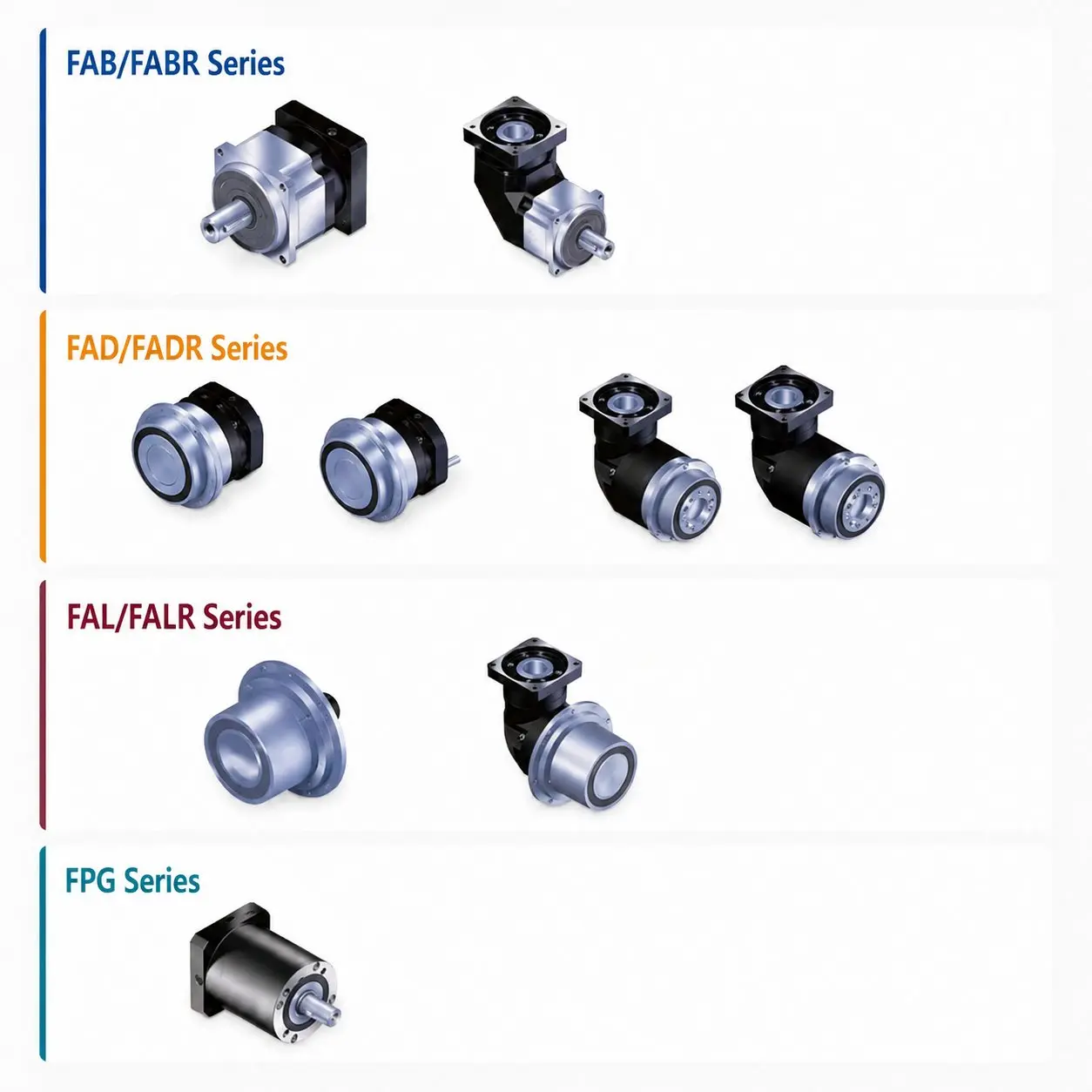
Korea Ever-Power EP series planetary gearbox range — EP-FAB square flange high torsional stiffness vs EP-FAD round flange for stiffness-critical applications

 Browse the full EP series catalogue. Related technical guides: the grade selection guide (backlash error budget) and the service life guide (L10 bearing life) together with this guide (compliance error budget) form the complete gearbox specification framework. External resources: cvjointdriveshaft.com.

Frequently Asked Questions — Torsional Stiffness

Can I improve torsional stiffness by using a higher gear ratio in the same frame?
Changing the gear ratio within the same series and frame size has a modest effect on torsional stiffness because the number of planet gear tooth engagements changes slightly with ratio, and the planet gear size relative to the ring gear changes. In general, higher ratios (fewer teeth, larger planet gears relative to ring) produce marginally higher Ct because the gear mesh contact area is proportionally larger. However, this effect is small compared to the difference between FAD and FAB at the same frame size, and between frame sizes. If your compliance calculation shows that the current series is insufficient and you are considering a ratio change to gain stiffness, Korea Ever-Power can confirm whether the Ct difference between ratios is significant enough to close your compliance gap — in most cases it is not, and upgrading from FAD to FAB or to the next frame size is the correct approach.
Does torsional stiffness decrease over service life as the gearbox wears?
Yes, but slowly and predictably. As bearing wear accumulates over service life, the output bearing clearance increases slightly, which reduces the torsional stiffness contribution from the output bearing pair. At the same time, gear tooth surface wear increases tooth-to-tooth clearance, which slightly increases backlash and marginally reduces gear mesh stiffness. Both effects are gradual — the torsional stiffness at 25,000 hours may be 5–15% lower than the initial Ct depending on the operating torque and duty cycle. This gradual stiffness reduction is the reason Korea Ever-Power recommends including a compliance error margin in precision application specifications — design to 80–85% of the available Ct to account for the expected reduction over service life. The service interval backlash measurement protocol (described in the Grade Selection and Service Life guides) also captures bearing wear trends that indicate when compliance is degrading toward the end of the design life.
Is EP-FAB appropriate for applications that currently use harmonic drive because of high stiffness?
Possibly — but it depends on whether the harmonic drive specification was driven by stiffness or by backlash requirements. Harmonic drives typically achieve Ct values of 20–80 N·m/arc-min depending on size and ratio, which overlaps significantly with EP-FAB’s range. If a harmonic drive was specified for a joint primarily because of its high torsional stiffness (common for robot J1/J2 base joints on heavier payload robots), EP-FAB P0 may achieve equivalent or superior stiffness at the same frame size with a significant service life advantage (30,000 hr vs 5,000–15,000 hr HD flexspline life) and efficiency advantage (97–99% vs 70–85%). If the HD was specified for near-zero backlash that cannot be achieved by P0 planetary with compensation (typical for ultra-precision inspection stages), the stiffness comparison is secondary and HD remains the correct choice. Run both the backlash grade calculation and the compliance error calculation for the specific joint to determine which specification drives the technology selection.
Where do I find confirmed Ct values for specific EP-series frame sizes and ratios?
Confirmed Ct values for specific EP-series, frame sizes, and ratios are available from Korea Ever-Power’s product technical data sheets — request the relevant datasheet by series and frame size from [email protected]. The indicative values shown in this guide’s bar chart are representative for the 090mm frame at mid-range ratios; actual Ct varies with frame size (proportionally higher for larger frames), ratio (marginally higher at higher ratios), and test load direction (Ct measured at rated output torque in the radial load direction). For specification-critical applications where compliance error is a significant portion of the positional error budget, request the confirmed Ct value for the specific frame/ratio/load direction combination before finalising the specification. Korea Ever-Power can also perform an application-specific compliance error calculation if you provide the applied torque, accuracy specification, and arm radius — the result identifies whether the current series satisfies the compliance budget or whether a stiffness upgrade is required. For robot arm applications specifically, Korea Ever-Power recommends providing the full joint loading table — the torque at each joint at the worst-case payload position — rather than just the rated payload, because the worst-case joint torque may be significantly lower than the rated joint torque (robots typically operate below rated payload for most tasks), and the compliance error calculation using actual duty torques produces a more accurate and often less conservative specification result. Engineers who have been specifying EP-FAB for robot joints where EP-FAD’s Ct is actually sufficient for the actual operating conditions — because they used the rated joint torque rather than the typical operating torque in the compliance calculation — can often switch to the less expensive EP-FAD without sacrificing compliance performance. The calculation takes 15 minutes with accurate joint loading data and saves the cost premium between FAB and FAD across all joints in the robot BOM.

Get Confirmed Ct and Compliance Error Calculation for Your Application
Send your applied torque, accuracy specification, axis radius, and the EP-series you are considering — Korea Ever-Power will provide the confirmed Ct value, calculate the compliance error, and confirm whether the series satisfies your compliance budget or recommend a stiffer series or frame size. Response within one business day.

Request Ct Calculation for Your Axis →

Editor: Cxm