Engineering Context
One Series, Two Configurations — What EP-FADS Removes and What Happens When It Does
Axial Dimension Comparison — Where the 22mm Comes From
The diagrams below show the axial stack of EP-FAD (with standard adapter ring) versus EP-FADS (direct-insert) for the same motor and gearbox combination. Each component’s approximate axial contribution is shown, with the total assembly length and the dimension savings labelled.
Crevice at adapter-to-housing joint — circumferential, cannot be fully cleaned
Smooth continuous housing face — no crevice, full surface cleanability
(typical)
Eliminated
Input End
IP, Speed
Dimensions shown are representative for EP-FADS / EP-FAD 060–090 mm frame sizes. Actual adapter ring thickness and clamp ring thickness vary by C-code and frame size — confirm exact dimensions from Korea Ever-Power’s dimensional drawings for the specific motor and frame size combination. The gearbox body dimensions (planetary stages, output shaft) are identical between EP-FAD and EP-FADS.
Selection Logic
When FADS Matters and When FAD Is Equally Good — The Three Selection Cases
The choice between EP-FAD and EP-FADS falls into three distinct cases. In Case A, the 22 mm axial saving is genuinely decisive for the design. In Case B, the crevice-free input face is the primary driver, even when axial space is not the constraint. In Case C, neither factor matters and the choice is arbitrary — FAD is typically easier to specify because the C1–C10 adapter system accommodates any motor without confirming shaft dimensions.
Complete Comparison
EP-FAD vs EP-FADS — Complete Specification Comparison
The table below shows every specification parameter for both series. Parameters highlighted in amber are the ones that differ; all other parameters are identical. The practical implication: specifying FADS where FAD would technically work costs nothing in performance — the only cost is confirming the motor shaft diameter against the FADS bore specification.
The identity of gear train, lubrication, and sealing between FAD and FADS has a direct consequence for machine qualification documentation. In medical device development under EU MDR or IEC 60601, each component in the drive train must be qualified against its relevant standard. Because EP-FAD and EP-FADS share the same internal gear train, the backlash grade testing (per-unit stamp), IP pressure test record, and gear accuracy documentation are directly transferable between the two series. An OEM who has qualified EP-FAD P0 for a robot prototype and subsequently moves to EP-FADS P0 for the production version — because the production enclosure is tighter — does not require a new gear performance qualification. The mechanical performance parameters (backlash, life, rated torque, IP) are unchanged. Only the motor interface configuration changes, and the shaft-compatibility confirmation for FADS takes the place of the C-code qualification for FAD. This documentation portability significantly reduces the re-qualification effort when transitioning from prototype to production on a constrained-space design.
A second implication of the identical gear train is that EP-FAD and EP-FADS gearboxes can be used interchangeably as spare parts within the same machine, provided the motor interface is adjusted. If a FADS unit on a production machine requires replacement and only FAD stock is available (or vice versa), the replacement is possible by adding or removing the adapter ring assembly — the gear train, output shaft, and all downstream mechanical connections remain compatible. This spare parts flexibility is valuable in production environments where machine downtime has a high cost and spare parts inventory is managed for cost efficiency.
| Parameter | EP-FAD (with C-series adapter) |
EP-FADS (direct-insert) |
Different? |
|---|---|---|---|
| Motor input interface | C1–C10 adapter ring + external clamp ring Adapter ring bolts to input housing |
Motor shaft inserts directly into gearbox bore No external adapter plate |
YES |
| Total axial length (gearbox + motor interface) |
Gearbox body + 18–22 mm Adapter plate + clamp ring |
Gearbox body only Zero additional axial |
YES |
| Input face crevice | Circumferential crevice at adapter-housing joint ~0.1–0.3 mm wide, ~5–8 mm deep |
None — smooth housing face Wiped clean in single pass |
YES |
| Motor mounting method | Motor bolts to adapter ring Standard C-code bolt pattern |
Motor bolts directly to gearbox input housing face Motor-specific bolt pattern |
YES |
| Motor shaft diameter confirmation |
Not required — clamp ring accommodates range C-code specifies pilot, not shaft ∅ |
Required — must fall within FADS bore tolerance Confirm shaft ∅ at order |
YES |
| Gear train (ring, planet, sun) | ✓ Identical | ✓ Identical | No |
| Backlash grades (P0/P1/P2/Std) | ✓ Same grades available | ✓ Same grades available | No |
| Gear ratios | ✓ Same catalogue ratios | ✓ Same catalogue ratios | No |
| Output shaft dimensions | ✓ Identical | ✓ Identical | No |
| Frame sizes (047–255 mm) | ✓ Full range | ✓ Full range | No |
| Max input speed | ✓ 6,000–10,000 rpm | ✓ 6,000–10,000 rpm | No |
| IP rating | ✓ IP65 every unit | ✓ IP65 every unit | No |
| Lubrication | ✓ NYOGEL 792D sealed | ✓ NYOGEL 792D sealed | No |
| Design life | ✓ 30,000 hr S1 | ✓ 30,000 hr S1 | No |
| Per-unit backlash stamp | ✓ Yes (P0/P1 measured value) | ✓ Yes (P0/P1 measured value) | No |
| Gear accuracy class | ✓ DIN Class 5 | ✓ DIN Class 5 | No |
| Unit price (same grade) | ✓ Equivalent | ✓ Equivalent | No |
Rows highlighted amber differ between EP-FAD and EP-FADS. Green rows are identical. EP-FAD and EP-FADS are the same gearbox with different motor input interface configurations — not different product families.
Application Examples
Six Application Examples — Choosing Between FAD and FADS
Ordering Guide
How to Specify EP-FADS — Motor Shaft Confirmation and Order Format
The one additional step for ordering EP-FADS compared to EP-FAD is confirming that the motor output shaft diameter falls within the FADS input bore range for the selected frame size. This confirmation replaces the C-code selection step — instead of specifying a C-code, you specify the motor shaft diameter (or model number from which Korea Ever-Power determines the shaft diameter).
The motor shaft diameter confirmation is a simple lookup, not a calculation. Korea Ever-Power maintains a reference table of output shaft diameters for all major servo motor brands and model series. When you send the motor model number, the application engineering team cross-references it against this table to confirm the shaft diameter, then checks the FADS bore specification for the ordered frame size. In the overwhelming majority of cases, the answer is a one-line confirmation: the shaft diameter is within the rated bore range and the FADS specification is confirmed. The only situations where this step requires more than one business day are: motors not in the standard reference table (unusual brands or very recent model releases), motor variants with non-standard shaft configurations (special shaft ends, keyed shafts that affect the bore-to-shaft fit), or frame size combinations where the motor shaft is at the extreme of the bore tolerance range and a tighter tolerance bore must be specified as a production option.
For machine designers building a product line with multiple robot models using the same motor platform, a single shaft confirmation covers all machines in the line — once Korea Ever-Power has confirmed that a Yaskawa SGMJV-08 shaft is compatible with EP-FADS 060, that confirmation applies to every subsequent order of the same combination. The design documentation note “EP-FADS 060 bore confirmed for SGMJV-08 shaft ∅ 14h6 on [date], reference KE-FADS-2026-0xxx” provides traceability for the machine’s technical file in the same way that a C-code qualification document does for EP-FAD.
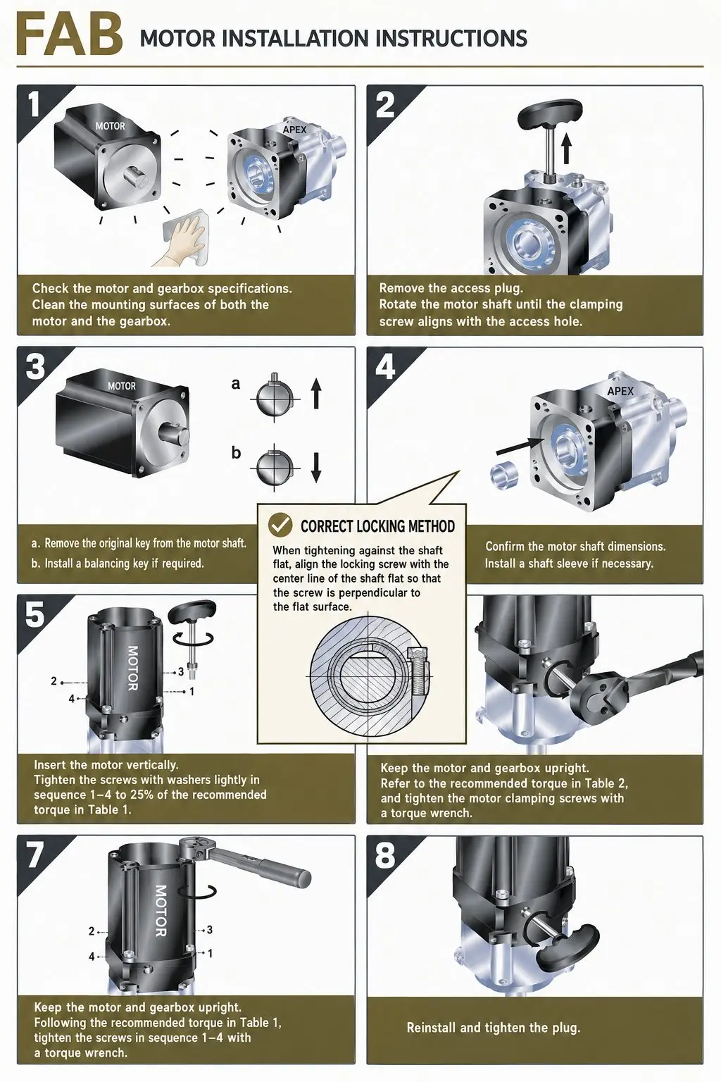
The shaft-to-bore interface in EP-FADS uses a split clamp ring integrated into the gearbox input bore — the same friction-preload principle as the external clamp ring in the C-series adapter, but machined as part of the FADS housing. The clamp bore contracts radially under bolt torque to grip the motor shaft. As with the external clamp ring, this produces zero angular play between the motor shaft and the gearbox input — the shaft and gearbox rotate as a single rigid assembly. The clamp bolt torque specification for FADS is provided by Korea Ever-Power per frame size and shaft diameter; this is the single installation parameter that the assembler must confirm and record, analogous to the adapter ring bolt torque in EP-FAD assembly. The shaft minimum engagement depth specification — the minimum length of motor shaft that must be inserted into the FADS bore before the clamp is tightened — is equally critical: insufficient engagement reduces the friction contact area and lowers the coupling’s torque transmission capacity below the rated value. Korea Ever-Power provides both the clamp bolt torque and the minimum engagement depth in the FADS installation data sheet, which is supplied with every unit and available in advance from application engineering when requested for assembly procedure documentation.
An important maintenance consideration for FADS: because the clamp ring is internal to the gearbox housing, it is not accessible for re-torquing after the housing is sealed. This is not a limitation in normal operation — the clamp bolt torque, once set at assembly, remains stable indefinitely because the preload acts on a steel shaft in a steel clamp ring bore with no dynamic loads that would cause relaxation. However, it does mean that if a motor is removed from a FADS gearbox and re-installed (for example, during a motor replacement on a production machine), the assembly team must follow the FADS installation procedure for the re-installation, including confirming the clamp bolt torques after re-seating the motor shaft. Korea Ever-Power’s installation data sheet covers this procedure for each frame size and shaft diameter combination.
For applications where the motor is not yet selected at the time of the gearbox procurement decision (a common situation in early-stage machine design), EP-FADS can be ordered with a “bore to suit” specification — providing the target shaft diameter range from the prospective motor shortlist, and Korea Ever-Power confirms which FADS bore specification covers that range. This approach allows the gearbox procurement to proceed in parallel with the motor selection process, reducing the programme schedule risk from sequencing the two supplier qualifications.
Related EP-Series and Technical Guides
Frequently Asked Questions — EP-FADS vs EP-FAD
Editor: Cxm