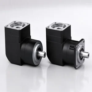
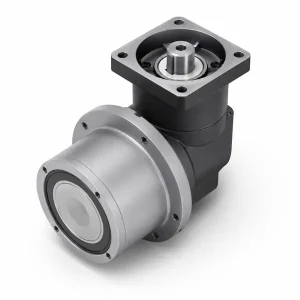
EP-FADR 시리즈 직각 고속 유성 기어박스 | 원형 플랜지 90°

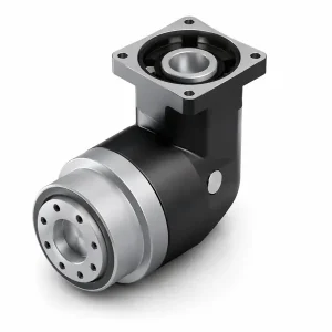
90° 직각 출력
고속 · 긴 수명
EP-FADR 시리즈 — 원형 플랜지 직각 유성 기어박스
완벽한 직각 패키지: EP-FAD 원형 플랜지 고속 플랫폼 ~와 결합됨 90° 베벨 기어 출력단최대 입력 10,000rpm, 설계 수명 30,000시간 - 고처리량 직각 서보 축용.
최대 2,000Nm
i = 4 – 200
30,000시간 수명
IP65
EP-FADR은 한국 Ever-Power 제품군에서 어떤 위치를 차지할까요?
| 시리즈 | 출력 플랜지 | 출력 방향 | 최대 입력 속도 | 디자인 라이프 | 가장 적합한 대상 |
|---|---|---|---|---|---|
| EP-FAB | 정사각형 | 인라인 | 10,000 rpm | 20,000시간 | CNC, 로봇, 일반 서보 |
| EP-FABR | 정사각형 | 90도 직각 | 10,000 rpm | 20,000시간 | 직각 레이아웃, 코너 드라이브 |
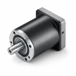
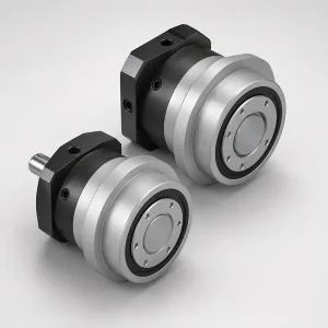
| EP-FAD | 둥근 | 인라인 | 10,000 rpm | 30,000시간 | 반도체, FPD, 회전 테이블 |
| EP-FADR ★ | 둥근 | 90도 직각 | 10,000 rpm | 30,000시간 | 고속 + 원형 플랜지 + 직각 — 이 세 가지 모두 |
EP-FADR은 한국 에버파워 유성 기어박스 제품군 중 가장 완벽한 사양을 갖춘 직각 모델입니다. EP-FAD의 장점을 계승합니다. 원형 플랜지 고속 플랫폼 — 최대 입력 10,000rpm, 설계 수명 30,000시간 — 그리고 출력축을 90°로 전환하는 정밀 베벨 기어 출력단을 추가했습니다.
EP-FABR(직각 플랜지)과 비교하여 EP-FADR은 원형 볼트 서클 플랜지를 사용합니다. 볼트를 직접 ISO 표준 원형 플랜지 회전 테이블, 액추에이터 하우징 및 로봇 링크 암에 적용하여 사각형 플랜지 인터페이스에 필요한 어댑터 플레이트를 제거하고 어댑터로 인해 발생할 수 있는 동심도 오차를 없앱니다.
- ◉원형 볼트 서클 플랜지 — ISO 원형 플랜지와 직접 연결, 어댑터 플레이트 불필요
- ◉최대 입력 회전수 10,000rpm — 초고속 서보 모터 및 선형 모터 구성 지원
- ◉30,000시간 설계 수명 — 총 수명주기 유지보수 비용을 최대 50%까지 절감
- ◉최대 200:1의 2단계 압축비 - 탠덤 기어박스 장치 불필요
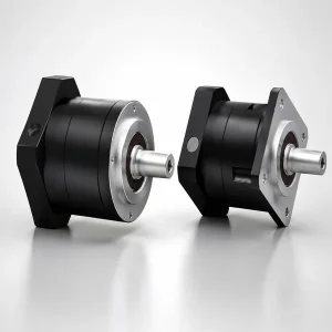
- ◉출력 하우징은 모든 기계 레이아웃에 맞게 90도씩 4방향으로 회전 가능합니다.
EP-FADR: 7가지 프레임 크기, 0.47~255mm, 원형 플랜지 직각 출력
프레임 크기 범위 — EP-FADR047 ~ EP-FADR255
EP-FADR 시리즈 기술 사양
| 매개변수 | EP-FADR047 | EP-FADR064 | EP-FADR090 | EP-FADR110 | EP-FADR140 | EP-FADR200 | EP-FADR255 |
|---|---|---|---|---|---|---|---|
| 정격 출력 토크 T₂ₙ (Nm) — 1단, i=4–20 | |||||||
| i=4 | 19 | 48 | 130 | 270 | 560 | 1,100 | 1,700 |
| i=5 | 22 | 60 | 160 | 330 | 650 | 1,200 | 2,000 |
| i=7 | 19 | 50 | 140 | 300 | 550 | 1,100 | 1,800 |
| i=10 | 14 | 40 | 100 | 230 | 450 | 900 | 1,500 |
| i=14 / i=20 | — | — / 40 | — / 100 | — / 230 | — / 450 | — / 900 | — / 1,500 |
| 정격 출력 토크 T₂ₙ (Nm) — 2단, i=25–200 | |||||||
| i=25–50 | 19~22세 | 48~60세 | 100~160 | 230~330 | 450~650 | 900~1,200 | 1,500~2,000 |
| i=100–200 | 14 | 40 | 100 | 230 | 450 | 900 | 1,500 |
| 성능 매개변수 | |||||||
| 최대 출력 토크 T₂ₘₐₓ | 정격 토크의 3배 (모든 사이즈) | ||||||
| 정격 입력 속도 nᵢₙ (rpm) | 5,000 | 4,000 | 3,000 | 2,000 | |||
| 최대 입력 속도 nᵢₙₘₐₓ (rpm) | 10,000 | 8,000 | 6,000 | 4,000 | |||
| 백래시 P0 — 초정밀도(arc-min) | ≤2 (1단계) / ≤4 (2단계) | ||||||
| 백래시 P1 — 정밀도(arc-min) | ≤4 (1단계) / ≤7 (2단계) | ||||||
| 백래시 P2 — 표준(최소 호) | ≤6 (1단계) / ≤9 (2단계) | ||||||
| 비틀림 강성 (Nm/arc-min) | 7 | 13 | 31 | 82 | 151 | 440 | 1,006 |
| 최대 굽힘 모멘트 Mₘₐₓ (Nm) | 42.5 | 125 | 235 | 430 | 1,300 | 3,064 | 5,900 |
| 허용 축력 F_ax (N) | 1,080 | 2,110 | 2,310 | 4,800 | 6,200 | 5,450 | 10,600 |
| 사용 수명(시간) | 3만 이상 | ||||||
| 효율 η — 1단계 / 2단계 | ≥95% / ≥92% | ||||||
| 무게 — 1단계 (kg) | 1.1 | 2.1 | 5.9 | 10.5 | 21.9 | 50.9 | 85.4 |
| 무게 — 2단계 (kg) | 1.4 | 1.9 | 4.5 | 9.8 | 20.1 | 45.4 | 85.9 |
| 작동 온도 | -10°C ~ +90°C | ||||||
| 윤활유 | NYOGEL 792D (합성, 수명) | ||||||
| 보호 등급 | IP65 | ||||||
| 장착 방향 | 어느 방향이든 | ||||||
| 소음 (nᵢₙ=3,000 rpm, dB) | ≤61 | ≤63 | ≤65 | ≤68 | ≤70 | ≤72 | ≤74 |
참고: 효율 ≥95% / ≥92%에는 베벨 기어 단계 손실이 포함됩니다. 인라인 EP-FAD는 ≥97% / ≥94%를 달성합니다. 구동계 효율이 주요 제약 조건인 경우 EP-FAD를 선택하십시오. * 연속 작동 수명은 정격 토크 50%에서의 평균 부하를 기준으로 합니다.
엔지니어링 특징
원형 출력 플랜지
볼트 서클 원형 플랜지는 ISO 표준 원형 플랜지 인터페이스와 직접 통합됩니다. 플랜지 직경은 EP-FADR047(D1=12mm)부터 EP-FADR255(D1=100mm)까지이며, 주요 회전 테이블 및 액추에이터 사양을 충족합니다.
90° 정밀 경사 출력
정밀하게 가공된 나선형 베벨 톱니 쌍은 출력 토크를 90°로 전환합니다. 모든 제품은 조립 후 톱니 접촉 패턴을 검증하여 백래시와 소음이 정격 사양 내에 있는지 확인합니다.
최대 입력 10,000 rpm
EP-FADR047 및 EP-FADR064는 최대 10,000rpm을 지원하며 반도체 장비에서 초고속 서보 모터 및 선형 모터 회전 변환 구성을 지원합니다.
30,000시간 설계 수명
베어링 선정 및 윤활 구조 개선을 통해 3만 시간(2교대 생산 기준 약 15년)의 수명을 달성하여 2만 시간급 기어박스 대비 총 수명 주기 유지 보수 비용을 크게 절감합니다.
4위치 출력 방향
경사각 출력 하우징은 90° 단위로 4단계 회전하여 출력 샤프트를 원하는 방향으로 조절할 수 있습니다. 현장에서의 위치 조정은 10분 이내에 완료되며, 유성 기어단이나 모터를 분해할 필요가 없습니다.
높은 굽힘 모멘트 등급
원형 플랜지 출력부는 42.5 Nm(EP-FADR047)에서 5,900 Nm(EP-FADR255)까지의 굽힘 모멘트를 견딜 수 있으며, 외부 지지 베어링 없이 캔틸레버 하중 구성을 지원합니다.
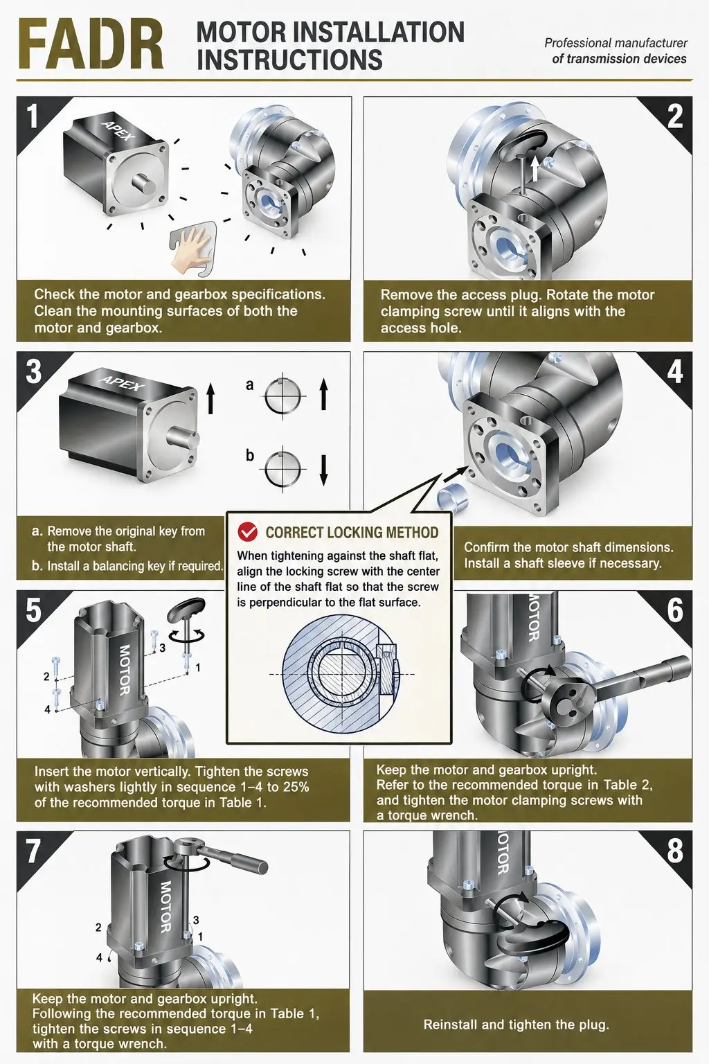
모터 조립 및 설치 시 유의사항
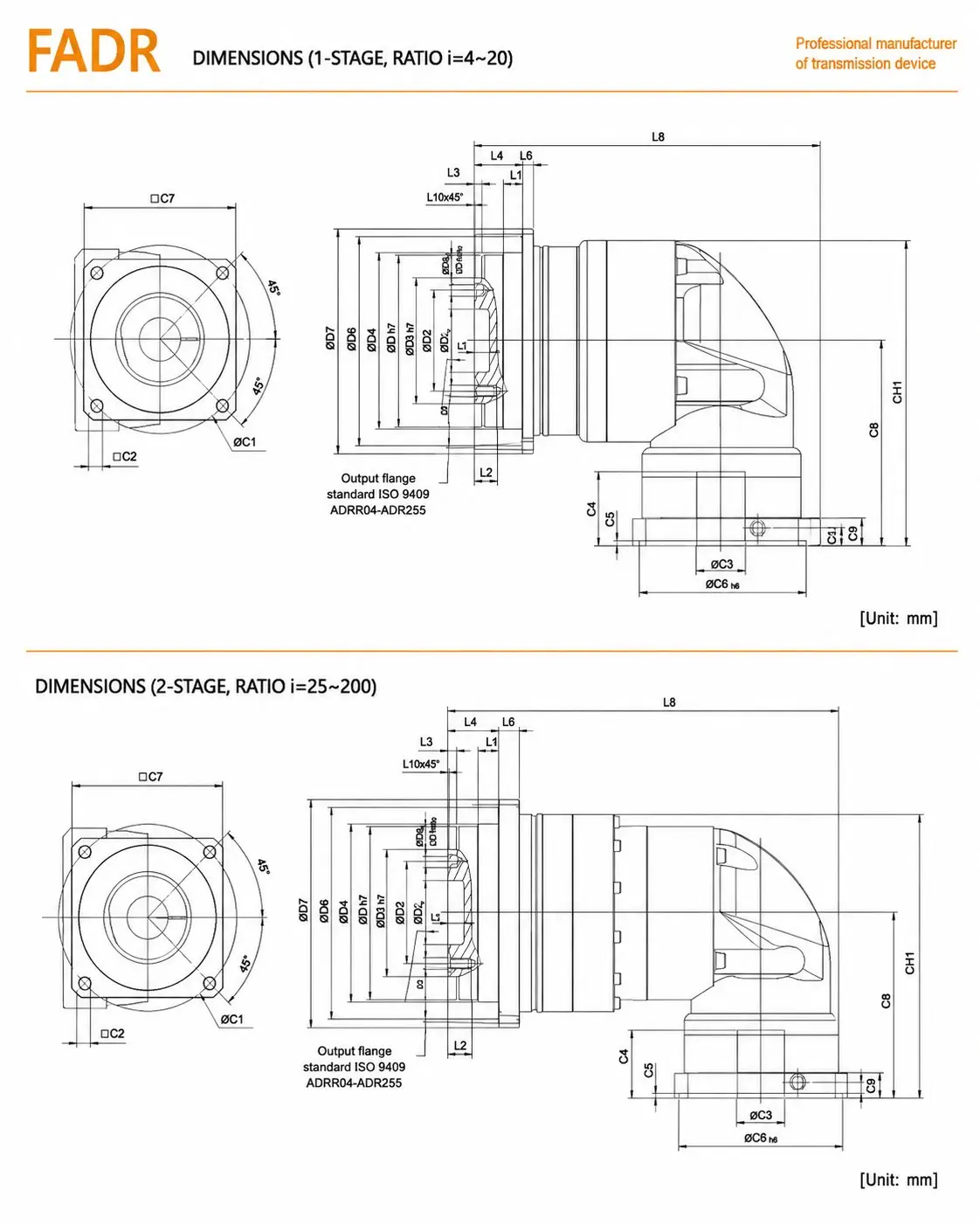
EP-FADR 출력 방향 조정 및 원형 플랜지 볼트 원 치수
모터 입력단은 EP-FAD와 동일한 클램프-링 어댑터 시스템(C1–C10)을 사용하며, 8단계 조립 과정도 동일합니다. 원형 플랜지 직각 구성에는 다음 세 가지 사항이 특히 중요합니다.
최종 조립 전에 회전 테이블 또는 액추에이터 볼트 원 직경(D8)과 나사산 피치(D9)가 선택한 EP-FADR 프레임과 일치하는지 확인하십시오. 강제 정렬로 인한 플랜지 면의 변형을 방지하기 위해 볼트를 십자형으로 조이기 전에 다웰 핀을 사용하여 초기 센터링을 하십시오.
스톱 핀을 조이기 전에 베벨 출력 하우징이 90° 위치로 정확하게 회전되었는지 확인하십시오. 하우징 고정 볼트 4개를 풀고 원하는 방향으로 회전시킨 다음 설치 설명서에 명시된 값으로 십자형 패턴으로 다시 조이십시오.
연속 회전 속도가 6,000rpm을 초과할 경우, 평균 토크 × 입력 속도 곱이 프레임 크기에 대한 열 출력 제한을 초과하지 않는지 확인하십시오. EP-FADR200 및 EP-FADR255는 최대 부하 상태에서 정격 속도로 작동할 때 강제 공랭식이 필요할 수 있습니다.
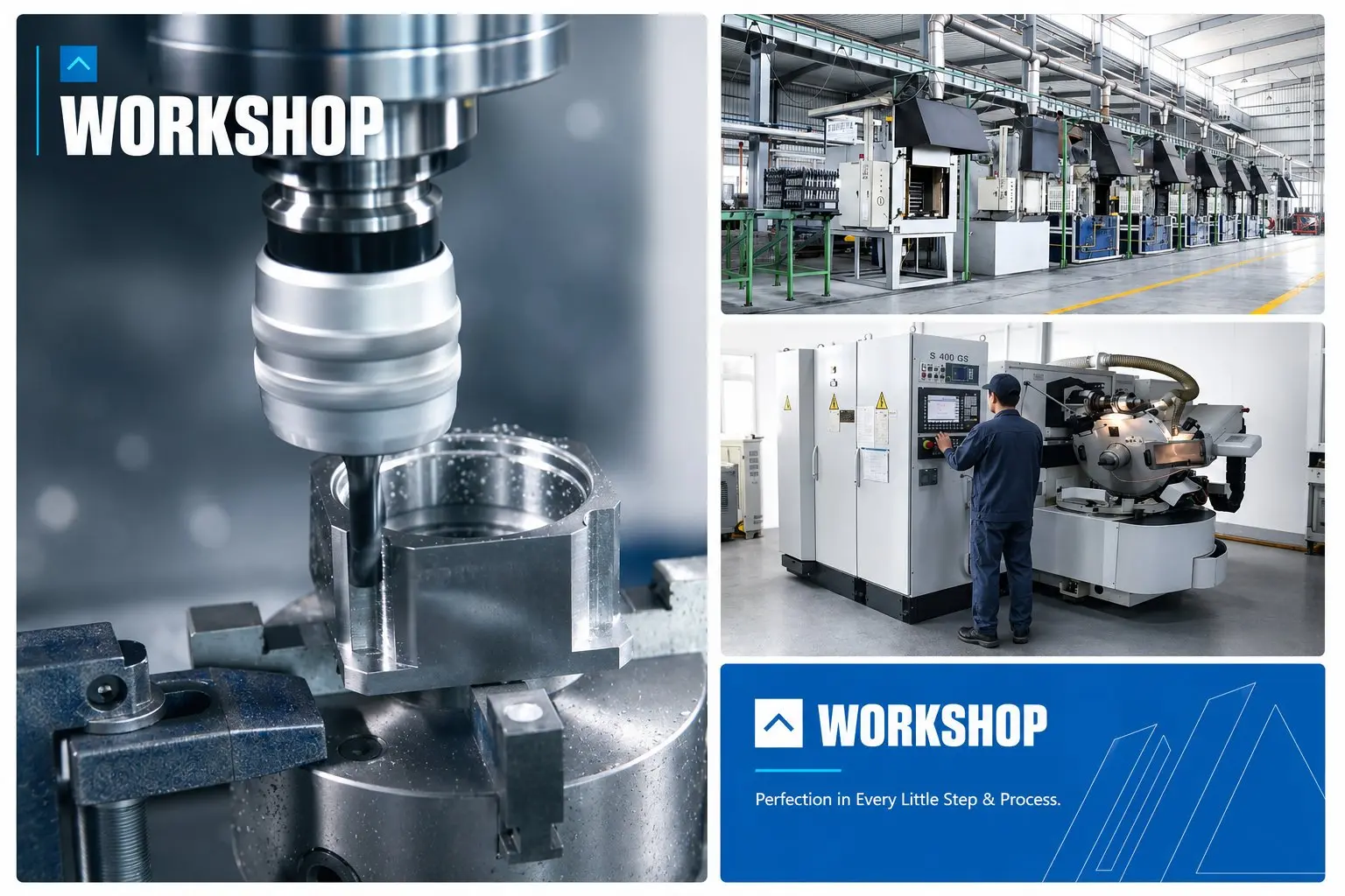
제조 및 품질 보증
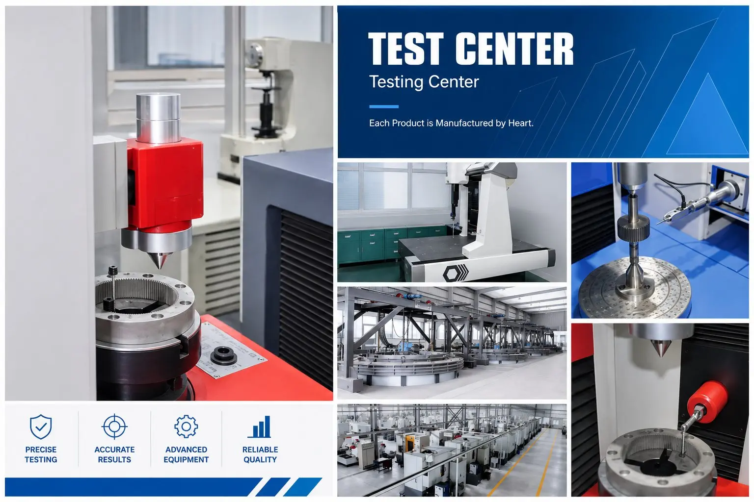
모든 EP-FADR 제품은 출하 전에 표준 5단계 품질 검사와 더불어 모서리 경사면 검사를 거칩니다.
- ◉DIN 5 프로파일 연삭 — 링 기어 및 유성 기어는 유럽 정밀 기어박스와 동일한 정밀도 등급으로 5축 CNC 프로파일 연삭 가공되었습니다.
- ◉고속 주행 테스트 — 모든 장치는 정격 입력 속도(소형 프레임의 경우 최대 10,000rpm)로 작동하여 베어링 예압 및 오일막 형성을 확인합니다.
- ◉경사면 접촉 패턴 확인 — 조립 후 마킹 컴파운드를 사용하여 치아 접촉 패턴을 확인합니다. 규격 미달 제품은 재작업 및 재검사를 실시합니다.
- ◉부하 소음 테스트 — 정격 속도 및 부하 상태에서 측정한 소음; 61~74dB(A) 이하를 초과하는 제품은 포장 전에 불량 처리됩니다.
- ◉개별 백래시 측정 및 등급 표기 — 개별 검증 후 명판에 P0/P1/P2 등급이 각인됩니다.
- ◉IP65 공압 밀봉 테스트 — 유성 기어 하우징과 경사형 출력 하우징 밀봉 인터페이스는 별도로 압력 테스트를 거쳤습니다.
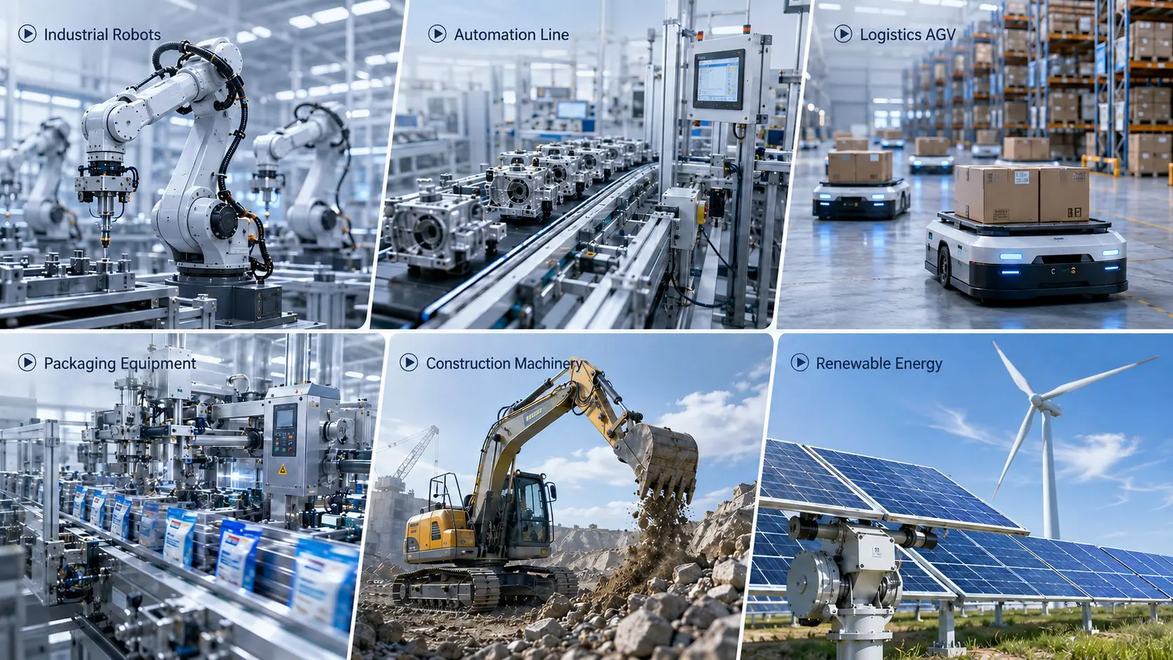
주요 응용 분야
반도체 장비
웨이퍼 이송 로봇의 직각 손목 관절은 원형 플랜지가 알루미늄 링크 암에 직접 볼트로 고정됩니다. 10,000rpm의 입력 속도와 30,000시간의 수명은 3교대 연속 IC 제조 환경에 적합합니다.
FPD 제조
대형 유리 패널 이송 로봇 손목 관절. 원형 플랜지 볼트가 주조 링크 구조에 직접 고정되어 설치 높이를 낮추고 로봇 팔 단면 관성 모멘트를 줄입니다.
CNC 직각 테이블
트러니언형 5축 가공센터의 B/A축 구동 장치. 원형 플랜지는 사각형 플랜지 기어박스의 어댑터 플레이트 높이를 없애 테이블 적층 높이와 강성 손실을 줄입니다.
권선기 및 풀림기
필름, 포일 및 배터리 전극 권선기에서 서보 모터 축은 맨드릴에 수직입니다. i=140~200의 2단 EP-FADR은 단일 장치에서 큰 직각 감속을 제공합니다.
고속 물류 분류
전자상거래 물류 분류 로봇용 직각 관절. 고속, 원형 플랜지 및 직각 관절이 하나의 유닛에 통합되어 부품 수를 줄이고 로봇 팔의 무게를 낮춥니다.
전기차 배터리 조립
배터리 모듈 적재 로봇 손목 관절. 원형 플랜지 볼트가 링크에 직접 고정되어 서보 모터가 배터리 트레이 내부에 접혀 들어가 로봇 팔 단면 폭을 최소화합니다.
주문 방법 — EP-FADR 주문 코드
EP-FADR 주문 코드는 EP-FAD와 동일한 구조를 따릅니다. 프레임, 기어비, 출력축 유형, 정밀 등급 및 모터 모델을 지정하십시오.
—
010
—
S1
—
피1
/
야스카와 SGMJV-04ADE6S
| 코드 필드 | 옵션 | 메모 |
|---|---|---|
| 모델 | EP-FADR047 / EP-FADR064 / EP-FADR090 / EP-FADR110 / EP-FADR140 / EP-FADR200 / EP-FADR255 | 출력 토크 및 원형 플랜지 볼트 서클 요구 사항에 따라 선택하십시오. |
| 비율 | 1단계: 4, 5, 7, 10, 14, 20 | 2단계: 25, 30, 35, 40, 45, 50, 60, 70, 80, 90, 100, 120, 140, 160, 180, 200 | 3자리 코드: "010" = i=10, "200" = i=200 |
| 출력축 | S1 = 매끄러운 원형 샤프트 | S2 = 스플라인/클램프 샤프트 | S1은 유연한 커플링용, S2는 견고한 직접 연결용입니다. |
| 정밀 등급 | P0 = ≤2 아크분 | P1 = ≤4 아크분 | P2 = ≤6 아크-분 | P1은 대부분의 직각 고속 서보 축에 권장됩니다. |
| 모터 | 모터 제조업체명 + 모델 번호 | 한국의 Ever-Power는 해당 클램프 링 어댑터 링을 제공합니다. |
보완 제품
원형 플랜지 + 인라인 출력 + 30,000시간 수명, 효율 ≥97%(1단). 레이아웃상 인라인 출력이 가능하고 구동계 효율을 극대화해야 할 경우 선택하십시오.
사각 플랜지 + 90° 직각 출력 + 20,000시간. 사각 플랜지 인터페이스가 표준인 경우 비용 절감; 동일한 P0 백래시(≤2 arc-min).
저렴한 가격의 직각 감속 장치로 자체 잠금 기능을 갖추고 있습니다. 서보 브레이크 없이 수직축 하중 유지가 필요한 저속, 저정밀 애플리케이션에 적합합니다.
EP-FADR 출력을 이동 로봇 관절 및 AGV 구동계의 관절형 또는 정렬 불량 하중축에 연결하기 위한 등속 커플링.
EP-FADR 변속기 사양을 정할 준비가 되셨습니까?
모터 모델, 필요한 출력 토크, 기어비, 원형 플랜지 볼트 서클 요구 사항 및 출력 샤프트 방향을 보내주십시오. 당사 엔지니어가 24시간 이내에 확정된 모델과 납기를 안내해 드립니다.
자주 묻는 질문
엔지니어들이 EP-FADR 시리즈에 대해 하는 말
반도체, FPD(고체 제품 포장) 및 정밀 자동화 산업 분야의 기계 제조업체로부터 받은 피드백입니다.
당사는 웨이퍼 이송 로봇의 손목 관절에 사용하던 유럽식 사각 플랜지 직각 기어박스를 EP-FADR090-P1으로 교체했습니다. 원형 플랜지는 알루미늄 링크 암에 직접 볼트로 고정되어 설치 높이를 14mm 낮추고 관절 단면 관성 모멘트를 약 18% 감소시켰습니다. 20개월간 연속 운전 후에도 백래시는 P1 규격 범위 내에 유지되었습니다.
"EP-FADR047은 9,200rpm 입력 속도로 16개월 동안 베어링 소음이나 백래시 증가 없이 작동했습니다. 30,000시간의 설계 수명은 교체한 기존 제품보다 약 50% 더 길어 웨이퍼 측정 플랫폼의 수명 주기 예비 부품 비용을 크게 절감할 수 있습니다."
"5축 트러니언 가공 센터의 B축에 EP-FADR110-P0 규격을 적용했습니다. 원형 플랜지가 테이블 하우징에 직접 중심을 맞추어 어댑터 심 조정이 필요 없었습니다. P0(≤2 arc-min)은 당사의 B축 위치 지정 사양을 충족했으며, 열 보정 계수를 조정한 후 윤곽 오차가 6 arc-sec 감소했습니다."
"4방향 출력 하우징 재배치 덕분에 배터리 모듈 적층기 개발 프로그램에서 상당한 시간을 절약할 수 있었습니다. 설계 단계에서 출력 샤프트 방향을 세 번 변경했는데, 매번 볼트를 풀고, 회전시키고, 다시 조이는 작업만 하면 되었고, 이 모든 과정이 10분 이내에 완료되었습니다. 어떤 단계에서도 기어박스를 다시 주문할 필요가 없었습니다."
"EP-FADR255 2단 구동 장치(i=140)는 서보 모터가 맨드릴 축에 수직으로 연결된 대형 필름 권선기를 구동합니다. 원형 플랜지는 맨드릴 끝 캡에 직접 볼트로 고정됩니다. 기존 솔루션과 비교하여 독립형 기어박스 유닛 하나를 제거했으며, 구동 체인은 4개 구성 요소에서 2개로 줄어들었고, 누적 백래시는 약 40% 감소했습니다."
추가 정보
| 편집자 | Cxm |
|---|
연관 상품
-
EP-WPBL/WPBF 시리즈 고정밀 직각 유성 기어박스 — ≤8 Arcmin, IP65, 90° 출력
-
EP-PBL/PBF 시리즈 고정밀 유성 기어박스 — ≤5 아크분 백래시, IP65 밀폐형
-
EP-FPG/EP-FPGA 시리즈 경제형 유성 기어박스 | 원형 및 사각형 하우징
-
EP-FALR 시리즈 일체형 타이밍 벨트 풀리가 장착된 직각 유성 기어박스
-
EP-FAL 시리즈 유성 기어박스(일체형 타이밍 벨트 풀리 포함)
-
EP-FADS 시리즈 어댑터 플랜지 고속 유성 기어박스 | 모터 직접 장착
-
EP-FAD 시리즈 고속 정밀 유성 기어박스 | 원형 플랜지
-

EP-FAB 시리즈 고정밀 유성 기어박스 | 사각 플랜지 인라인

